About the Author 📢
Sheetalkumar Patil is founder and director of Speed Engineering where they focus on engineering for a wide variety of segments like aerospace, automotive, electronics and so on. In this article though, the speed is much reduced as he takes us through the process of optimizing the aerodynamics of the famous Rickshaw at just 15 m/s.
Introduction
When people think of aerodynamics, they automatically think of airplanes flying at 800 km/h, rockets blasting into space or race cars lapping the Nürbürgring at insane speeds. But aerodynamics play a role as any object starts to move through the air, no matter how low the speed. And they start to play a significant role, i.e. an impact on fuel consumption & range well above 10%, at much lower speeds than people would expect. In this article, we dive into the details of the Rickshaw, one of the most popular vehicles in India & Sout-East Asia. And we come to the conclusion that much can be gained from improving its aerodynamics!
Bluff body aerodynamics
In fluid mechanics terms, vehicles are bluff bodies travelling very close the ground. A complex three-dimensional flow occurs around the vehicles with flow separation being very common. Such flow is typically analysed and optimized through external aerodynamics studies.
Sports cars, passenger cars and commercial vehicles - all of which move at relatively high speeds - experience significant aerodynamic drag forces which impact performance and increase fuel consumption. For ground vehicles, this is mainly pressure drag; so avoiding or reducing the separation is one of the main objectives of vehicle aerodynamics.
External aerodynamics is also becoming increasingly important in the shift from fossil fuel vehicles to electric vehicles. In the context of electrification of vehicles, the drag force is an important factor to be considered as it impacts the operating costs of the vehicles, sizing of the drive train and the range of the vehicle before recharge. Reducing drag force is important even for relatively slower speed electric vehicles and if not optimized, it can have significant impact on cost and performance. Therefore, design improvements through external aerodynamics simulations of drag resistance using CFD is a necessity for all electric vehicles.
External aerodynamics simulations using CFD though have some constraints, such as:
- Huge time required to create watertight geometry. This task is very tedious.
- High-end hardware requirement to reduce the analysis turnaround time (high RAM and number of CPU cores etc.).
- Huge computational costs. Major drawback of high-end computation is cost (hardware + software license). During the conceptual and preliminary design phases, these constraints may prove detrimental to the project's timeline and budget.
Here we are presenting a case study to depict how CFD analysis can be used to improve aerodynamics of a relatively slower speed commercial vehicle while overcoming the above constraints.
The Baseline Rickshaw Design
This case study has been performed on the legacy design of auto rickshaw (3-wheeler). It is mainly used as short distance taxi in India and South Asia. The body design was done in the last century and aerodynamic considerations were not the primary factors back then. If we want to convert such vehicle to an electric one, we need to consider aerodynamics and check how much electric power can be saved and also, if the range can be increased through design improvements to the body shape.
The shape of the 3-wheeler considered for this study is as shown below.
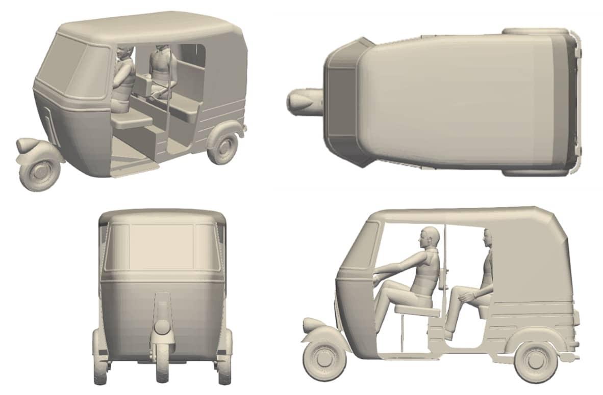
- This design is primarily used with a gasoline engine.
- Engine power rating is around 7.5 kW@4500 RPM with a peak torque of 19 Nm@3200 RPM
- Carries a maximum of 4 people - 1 driver + 3 passengers.
- The range of the vehicle is around 350km with full tank.
Revised Design
Based on the AirShaper results of the external aerodynamics study on the baseline design, the body shape was revised within the following constraints:
- Change in overall envelope should be minimal. No change in the ground clearance.
- No change in the drive-train interfaces (track, wheelbase etc.)
- Driver and passenger comfort should not be affected. No interiors should be affected.
- No major changes in ergonomics etc.
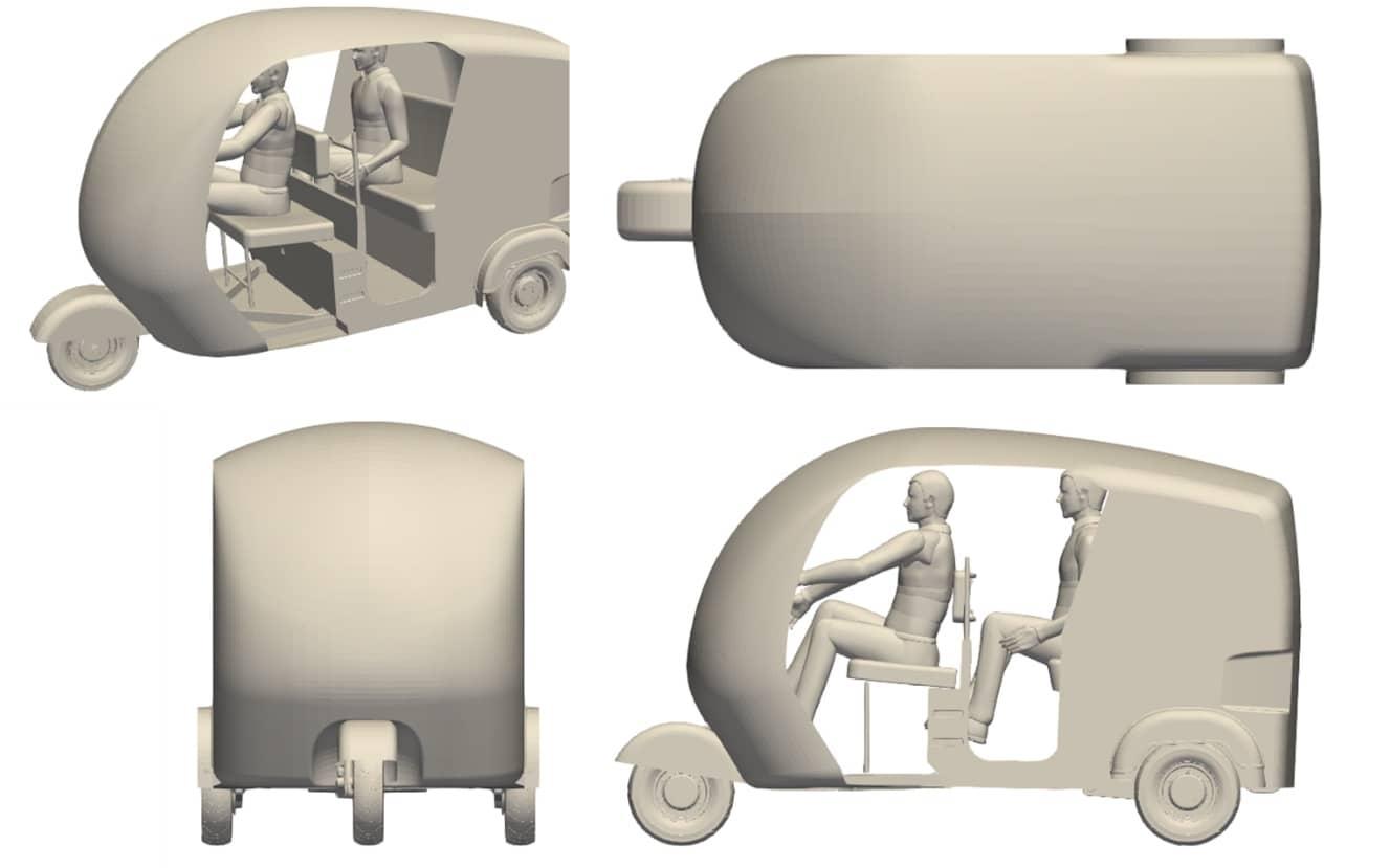
The following changes were made to the baseline design:
- The underfloor was made flat. All the steps are removed.
- The roof was given a downward slope towards the rear to delay separation.
- The frontal area was made more round.
- A feature just above the rear wheels was added to bleed air in the wake region.
The revised design is depicted below.
Simulation Results
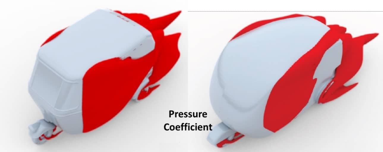
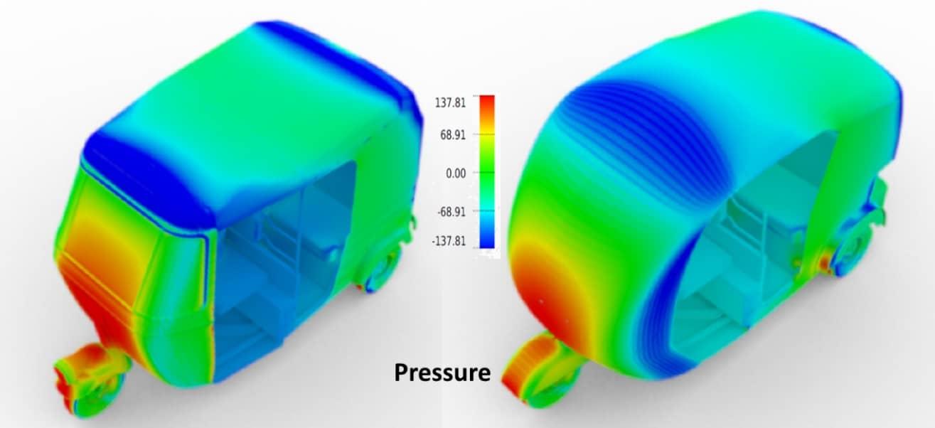
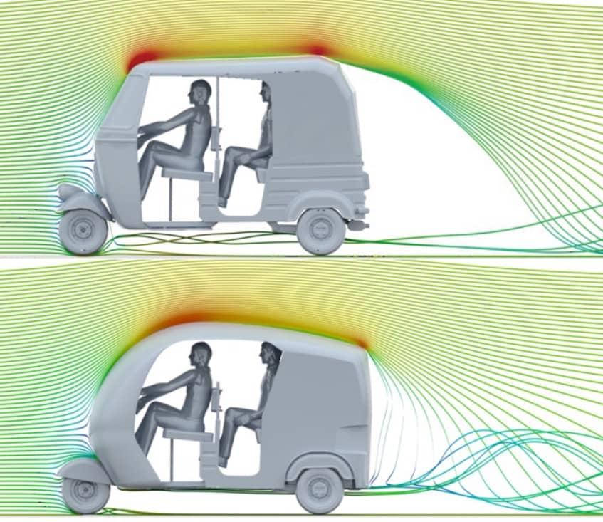
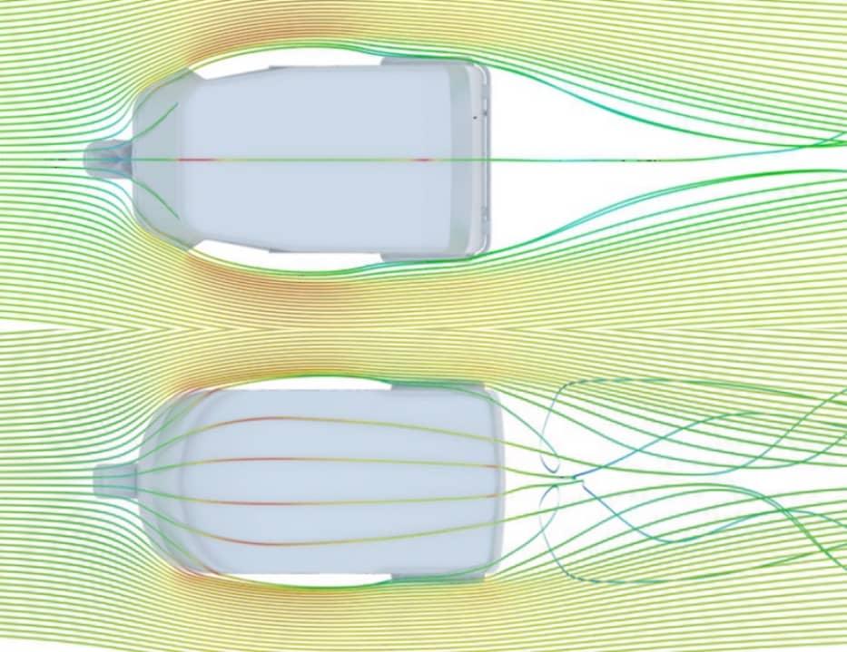
Both designs were analysed for aerodynamic performance at a vehicle speed of 15 m/s. The drag coefficient of the Rickshaw has dropped form 0.45 to 0.39. This reduces the power required to overcome aerodynamic forces by 17.4 %. This will result in an increase in the range of the vehicle as well.


The aerodynamic plots below, comparing the baseline & revised design, show how various aerodynamic considerations were implemented:
- The wake should be as small as possible (see "red clouds" behind the vehicle). This was achieved by an improved roof line, the removal of steps in the underfloor and the bleeding of air into the wake via slots on the sides of the vehicle.
- The pressure build-up at the front was reduced by increasing the radius of the front of the vehicle.
- The number & size of separation locations was reduced by eliminating steps at the underfloor, sharp edges at the front, and so on. The modifications done on the baseline geometry based on the recommendations by CFD analysis show significant improvement in the drag performance of the vehicle.
Efficiency
The total project was done in just 50 hours, of which 40% was CFD run time. The rest of the time was spent on geometry modifications, post-processing the data and drawing conclusions & reporting. So, computationally this is not a very expensive analysis.
Conclusions
- Estimating the performance parameters related to external aerodynamics by CFD during vehicle development can yield significant benefits even for relatively slow vehicles.
- Design improvements to the body shape based on external aerodynamics can help reduce drag, reduce power consumption and improve range. This is especially important for electric vehicles.
- The CFD analysis method presented here, gives an opportunity to perform external aerodynamics CFD analysis at very low cost and which is adequately accurate. In this arrangement, multiple CFD analysis iterations of external shapes are possible within a short timeframe.
Interesting links:
Running your own CFD Simulation
How to interpret a CFD Simulation
