Introduction
Always wanted to work in Formula One? Then join the Voyager-AirShaper F1 team!
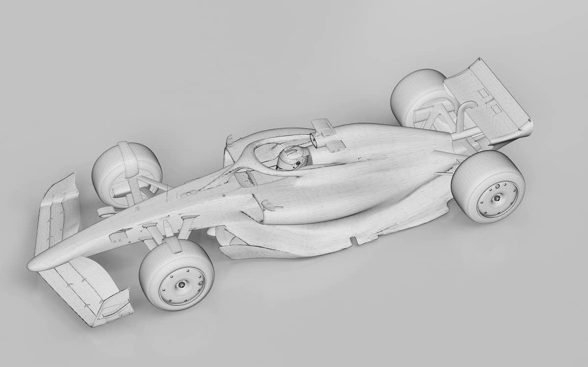
We've created a virtual challenge to optimize the aerodynamics of the Voyager-AirShaper F1 car through AirShaper simulations. The current design started life as a visual styling exercise - featuring a bespoke blue livery - 3D modelled by Voyager. But the car is just that – a styling model. A 3D model created to look stunning and realistic, but not engineered to perform well in terms of aerodynamics.
It doesn't comply with the official regulations, and we don't intend to make it comply. Rather, this exercise is about how you can tweak an existing design to perform better in terms of aerodynamics through modest and realistic changes. And we'll do so based in your input!
Reference
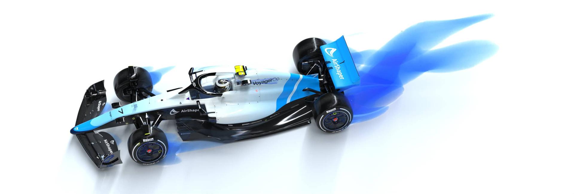
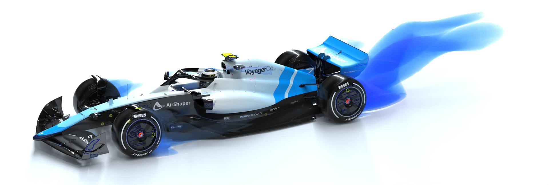
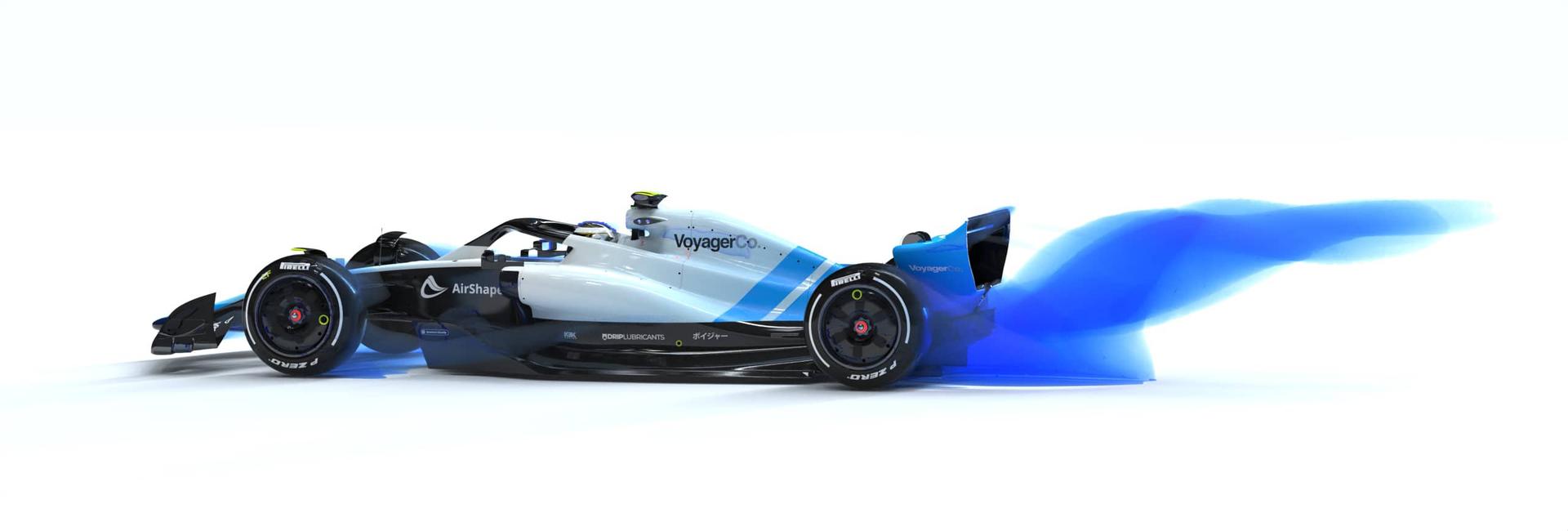
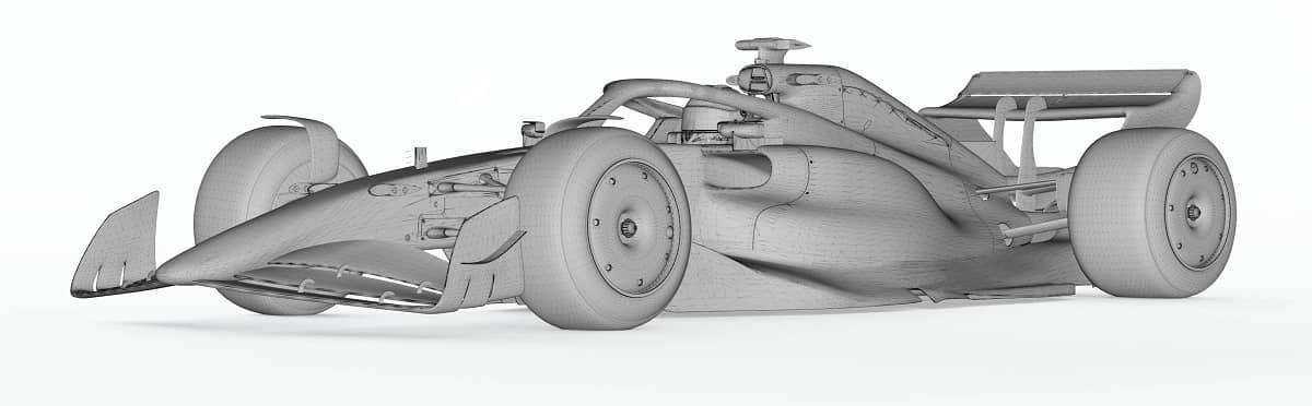
We've run aerodynamic simulations on the reference car – the current styling model. Both feature rotating wheels, moving ground and an adaptively refined mesh, but they differ in terms of accuracy:
| Regular Simulation | Advanced Simulation |
|---|---|
 |  |
| 12 Million Cells | 75 Million Cells |
| Drag coefficient Cd: 0.881 | Drag coefficient Cd: 0.896 |
| Lift coefficient Cl: -1.247 | Lift coefficient Cl: -1.523 |
| Front lift coefficient Cl(f) : -0.224 | Front lift coefficient Cl(f) : -0.302 |
| Rear lift coefficient Cl(r): -1.023 | Rear lift coefficient Cl(r): -1.222 |
| Download 3D model | Download 3D model |
| Download report | Download report |
| View online results | View online results |
| Download simulation data | Download simulation data |
This already poses the first challenge - which results will we use?
When it comes to running CFD simulations, you'll always need to make a compromise. Using the Regular Simulation will make it easier on your hardware to process data, the simulations will be faster and easier to run, etc. You'll be able to run more simulations with the same "teraflops" CFD budget, just like real F1 teams. If you're working on large flow structures, this may be enough. But when looking at small scale vortices, or need to mesh small details, it may not be sufficient.
For example, the downforce is higher on the Advanced simulation. In part, this is due to the fact that the Regular mesh was not detailed enough to capture the small gaps between the various wing elements. Actually, even on the Advanced simulation some gap areas are not captured properly!
Design challenge #1 Think carefully about which data to use for which area on the car.
Analyzing the data
We've added links to download the 3D model & report, to visit the online 3D results and to download the full simulation data. Again, we're facing challenges:
- 3D model: you'll notice the STL surface quality is fairly low in some locations (and it will likely not improve anytime soon). How does this affect results?
- Report: go through the full report and analyze the forces, the aero balance, the convergence graphs etc to get a feeling of how useful the simulation really is.
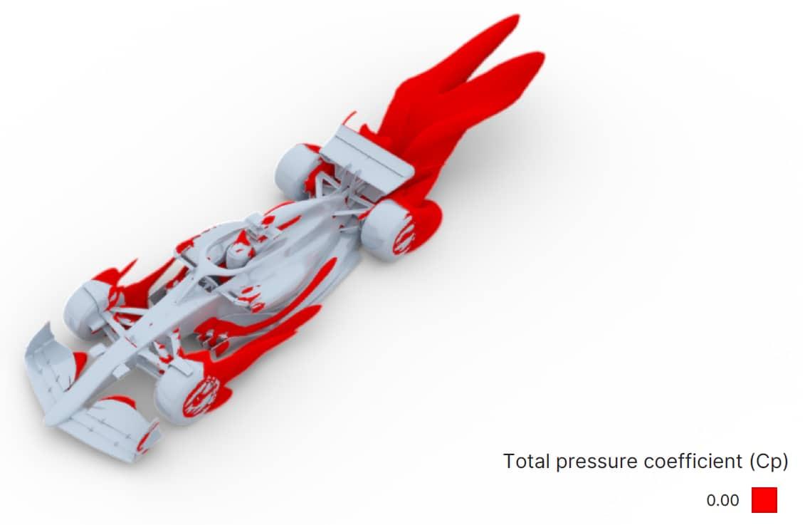
- Online visualizations: the 3D pressure clouds are particularly interesting to spot areas of flow separation / drag. Also, through the "Forces & moments" tab on the left, you'll be able to click on components to analyze their individual drag & lift (like the front wing etc).
- Simulation data: download the full simulation data and process the results in paraview – see this video. You can analyze every small detail in the flow by creating your own streamlines, pressure maps, and so on. Mastering paraview is a great skill for your aerodynamics career!
Design challenge #2 Use the online viewer and paraview to gain insights into the flow and share your findings.
Improving the car
The car does not comply with the official regulations and we don't intend to make it to. Nevertheless, the goal of this challenge is to come up with solutions that are realistic and stay close to the rules:
- Don't simply increase the size of the wing, reduce the size of the sidepods, … . That's too easy – no fun in that!
- Focus on improving flow quality in critical areas. Spot areas of separation and understand why it happens.
- If you have the time, please do go through the official F1 rules to support your suggestions.
We've set some arbitrary goals:
- Improved aero balance: not even 20% (-0.302 / -1.523 = 19.8%) of the downforce is going to the front wheels. The goal: increase the front downforce to 25%.
- More downforce: for circuits with lots of corners, downforce is crucial. So find ways to improve the overall downforce by 10%.
- More efficiency: the downforce to drag ratio is just 1.7 (1.523 / 0.896). Aim for a Cl/Cd ratio of 2.0 or more.
In reality, things are far more complex, with cars chasing each other, cornering simulations and so on. But for the sake of simplicity, we'll focus on an isolated car going in a straight line at a constant speed of 200 km/h.
Sharing your suggestions 
To achieve our goals, we will use your input!
Just drop your thoughts on the AirShaper Reddit channel (use the flair "Voyager-AirShaper F1"):
- Analysis: drop your insights on where you think the flow can be improved. Support your insights with post-processing screenshots of the 3D viewer / paraview.
- Suggestions: drop your sketches on how you think the 3D model should be modified.
- 3D model: if you want, you can also modify the 3D STL model directly. Contact us to get the Blender file.
We'll screen the Reddit channel regularly and gather design input. As soon as we have enough input, we will create an updated 3D model, run a simulation and share the results on the Reddit board!
Design challenge #3 : drop designs on the AirShaper Reddit channel
Aero Update 1
A big thanks to everyone who has contributed to the F1 challenge on our AirShaper Reddit channel! We sat together with the talented designers at Voyager to implement most of the suggestions, resulting in aero update 1 (Download 3D Model here):
Front Wing
- We implemented the design of Busor to have a more updated design
- The spacing between the wing elements was increased to avoid mesh bridging
- The sideplates were pushed inward at the front to reduce flow separation
The downforce on the front wing improved dramatically, with low pressure zones on the suction side being much more pronounced, now extending to the second and partially the third wing element.
Strakes
- The thickness of the strakes was reduced to avoid local flow separation
- The "inlet angle" of the strakes was increased, to point more inward.
- The "outlet angle" of the strakes was increased as well, to be outward instead of parallel to the driving direction of the car.
The result is less flow separation at the inlet and stronger vortices further downstream, resulting in a lower pressure and thus more pronounced suction effect across the majority of the underfloor.
BIB
The bib (sort of scoop around the central part of the underfloor) was added, grabbing some extra downforce (as the pressure on top of it pushes it downward - even though some of this is cancelled out as this higher pressure also acts on the surface above the BIB).
Other
Other small changes include updated barge boards and a different nose angle.
The result is Aero Update one, featuring massive performance improvements:
Original Car - View Online Results
- Drag Coefficient Cd: 0.896
- Lift Coefficient Cl: -1.523
- Aero balance: 19.8% front / 80.2% rear
Aero Update 1 - View Online Results
- Drag Coefficient Cd: 0.87
- Lift Coefficient Cl: -2.496
- Aero balance: 33.4% front / 66.6% rear
That's a 64% increase in downforce while reducing drag by 3%, combined with an improved aero balance (more downforce at the front). It's a no-compromise, pure improvement in aerodynamic performance!
We explain all of this in detail in the video below:
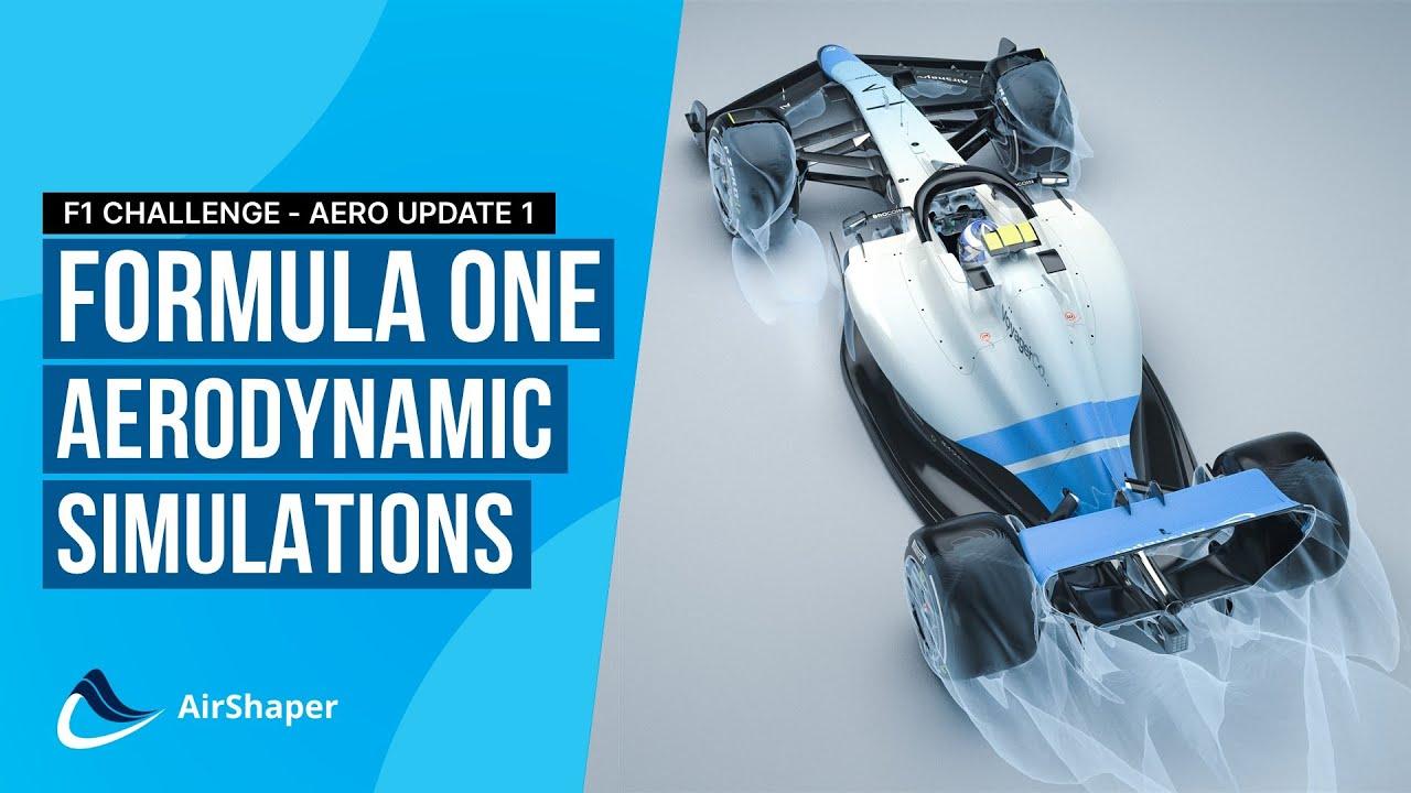
Improving F1 Aerodynamics using AirShaper CFD simulations - The Voyager-AirShaper F1 challenge
UPDATE: we found an error in the simuolation setup for Aero Update 1: the rear wheels were positioned slightly above the ground. This created a small gap between the wheels and the ground, creating a venturi channel (converging-diverging channel). This strong acceleration of the air lowered the pressure (because of the Bernoulli effect), creating downforce on both rear wheels. Once corrected, we found that the downforce gain was not 64% but 44%. Still massive, but not as much as claimed previously. This goes to show just how sensitive CFD and aerodynamics are to small changes - our apologies!
Aero Update 2
Again a massive thanks to everyone who has contributed to this second Aero Update. It was brilliant to see visuals, sketches and even YouTube videos appear on our AirShaper Reddit channel! As before, the guys at Voyager implemented most of the suggestions in 3D to get to aero update 2 (Download 3D Model here):
Sidepods
- The side pods were extended forwards
- At the top, more curvature was added to the front half of the side pod and less curvature at the rear half to keep the airflow attached all the way to the engineered
- In top view, the sidepod curvature starts earlier now, to have a less abrupt lateral push of the air outward. And the maximum width was reduced a bit, all to avoid the flow separation at the rear half of the sidepods.
The result is attached flow all the way to the rear of the sideopods. We still have a lot of flow separation at the inlets, as the air jumps across the sidepods. So there we still have room for improvement.
Strakes
- The inner fence was extended beyond the top of the underfloor to fight some of the flow curvature in that region
- The exit angle of the inner fence was reduced to avoid local flow separation
- The first, straight part of the fences was given a curvature. This curvature was gradually released towards the outward curvature of the fences, ti help initiate a stronger vortex. The result is a significant increase in downforce on the underfloor!
BIB
The BIB has been made sharper to reduce the local pressure buildup.
Rear Wing
The airfoil design was not changed (that is the topic for Aero Update 3) but we moved from a double support arm structure to a single one. Also, the swan neck geometry was pulled forward, to reduce the separation it induces at the suction side of the wing.
Other
- The mirrors are now connected directly onto the top of the sidepods, eliminating the hozirontal support arm. The remaining support arm below the mirror has an outward curvature, to remove some of the air at the top of the sidepods.
- The halo has been given a truncated section to reduce drag
The result is Aero Update two, featuring a further increase in downforce but in drag as well:
Aero Update 1 (corrected) - View Online Results
- Drag Coefficient Cd: 0.881
- Lift Coefficient Cl: -2.195
- Aero balance: 37.4% front / 62.6% rear
Aero Update 2 - View Online Results
- Drag Coefficient Cd: 0.91
- Lift Coefficient Cl: -2.437
- Aero balance: 36% front / 64% rear
That's a 11% increase in downforce at the cost of 3% more drag.
We explain all of this in detail in the video below:
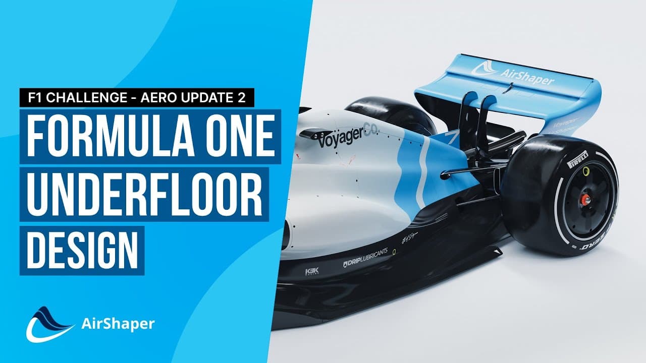
Formula One Aerodynamics Challenge - Part 2: side pods, underfloor, fences and more
Aero Update 3
We're happy with the added downforce but sad about the extra drag! So the goal for the third aero update is to reduce drag. We suggest working on the sidepods (flow separation at the intake) and the rear wing (we'll use proper airfoil designs this time) but all ideas are welcome! Just analyse the online results and download the 3D model to get started.
Deadline: Friday, Dec 23rd, 17:00 CET
The goals for this aero update:
- Maintain current downforce levels
- Reduce drag by 3%
If you wish to contribute, just head over to our AirShaper Reddit channel and drop your images / sketches / videos - thanks a lot!