Simulation of rotating elements of a quadcopter using OpenFOAM
Unmanned Aerial Vehicles (UAVs) are known for having a wide variety of applications ranging from landscape surveying, industrial inspection and monitoring, to precision agriculture and aerial imaging. The extensive use of UAVs can be linked to the cost-effective solutions provided by them. Important advantages of multirotored vehicles compared to single rotor vehicles are the increased lifting capacity, smoother vertical flight and safety redundancy. Moreover, lower manufacturing and production values combined with the lack of a human pilot decrease acquisition and operating costs significantly. Thus, there is a large shift across the aviation industry to use UAVs instead of conventional manned aircrafts.
On a general basis, UAVs are usually dimensioned and optimized for particular missions. This is where CFD can come in handy as it can predict the flow characteristics and help to further optimize the UAV for the mission it is designed for. Prediction of flow behaviour around a UAV is extremely challenging as the components are very tightly packed and there is little room for adjustments. Also, given the close proximity the tip vortex and wake from one propeller can mix up with the tip vortexes and wakes of the other propellers and the modeling of such flows becomes very complicated. CFD studies can be categorized into two areas; low and high fidelity methods. The high fidelity methods which can use unsteady flow models can help capture and predict these complicated flow behaviours whereas the low fidelity methods are not suitable for accurately predicting the unsteadiness of the flow. However, the low fidelity models are computationally cheap and offer a good co-relation which is why they are often used to perform iterative studies on UAVs.
AirShaper is an online platform that provides aerodynamic solutions for designers, engineers & architects where models can be uploaded and analyzed. The platform works by running a CFD simulation on an uploaded 3D model through their cloud based virtual wind tunnel. Founded in 2017, the company works with clients to improve the aerodynamic efficiency of their products.
The online platform’s current functionality is limited to static geometries that are either on or above the ground which can be either static or moving. A lot of the external aerodynamic studies involve implementing rotating elements to get accurate results, which could be the case for drones, wind turbines and even vehicles. The implementation of rotating elements is a drawback at the moment for the platform as it works only with static models.
To expand the platform’s reach into new markets and also get accurate results from running aerodynamic tests involving moving geometries, the company is investigating the use of rotating elements through this thesis. In CFD, there are different methods and approaches available to model rotating elements like the multiple reference frame (MRF) method, arbitrary mesh interface (AMI) method among others. The use and implementation of rotating elements can get quite complicated and
1 computationally expensive which is why prior research has to be conducted on the feasible methods that can be undertaken and also a comparison of the methods to investigate the superiority of one over the other.
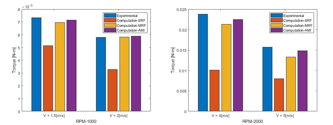
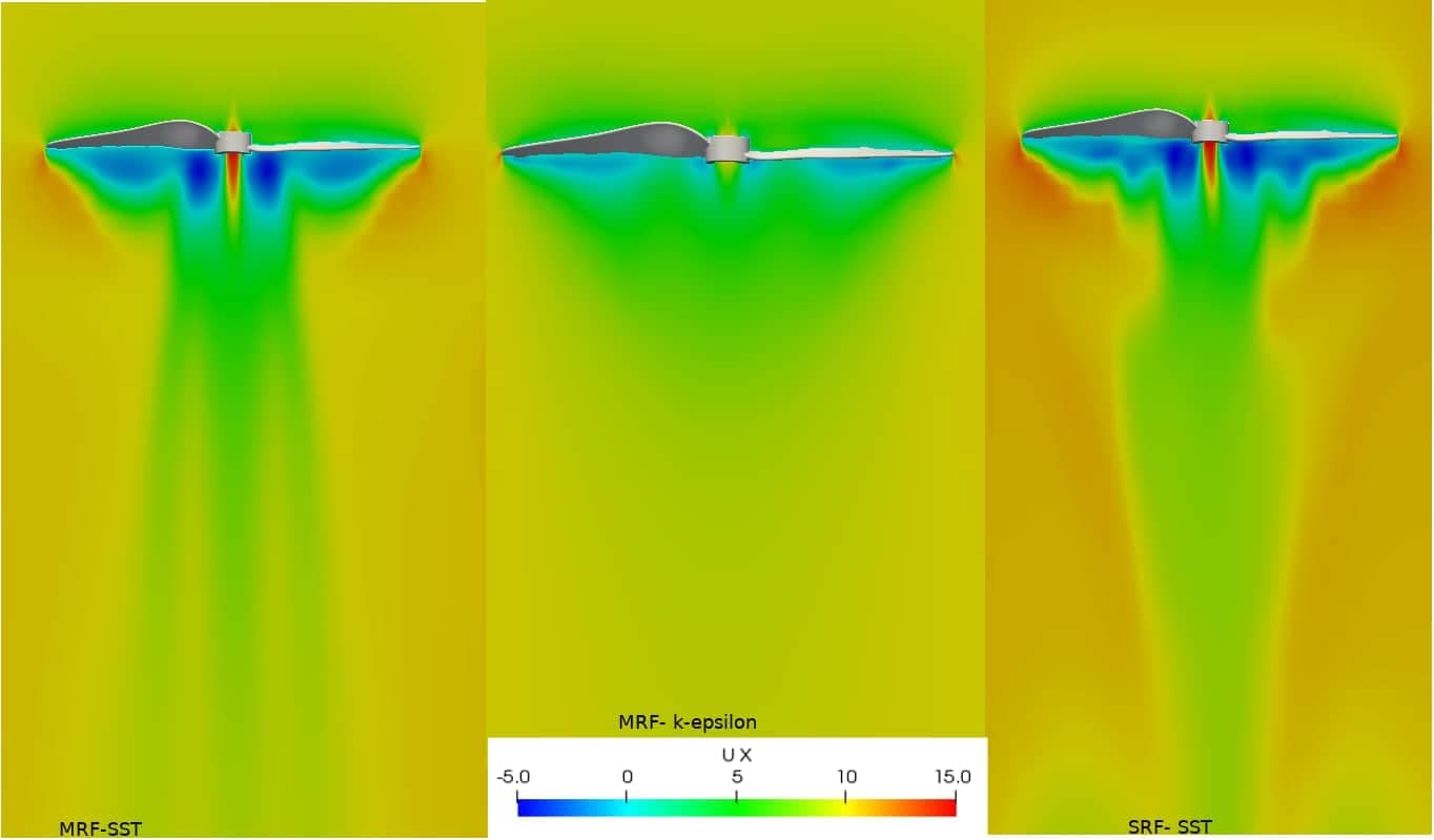
The scope of this thesis was therefore, to examine three methods, namely; the single reference frame (SRF) method, the multiple reference frame MRF) method and the arbitrary mesh interface (AMI) method, regarding their impact on accuracy, computational cost and feasibility towards commercial applications.
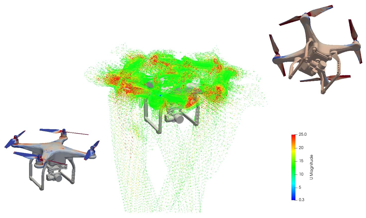
The respective methodologies are first established for a free-standing propeller and are tested on the propellers of the Dji Phantom 3, a common quadcopter used for commercial applications. Different tests are performed to understand the limitations and accuracy of each method and are presented in subsection 1.1.
Download Full Original Paper