
What is a standard model?
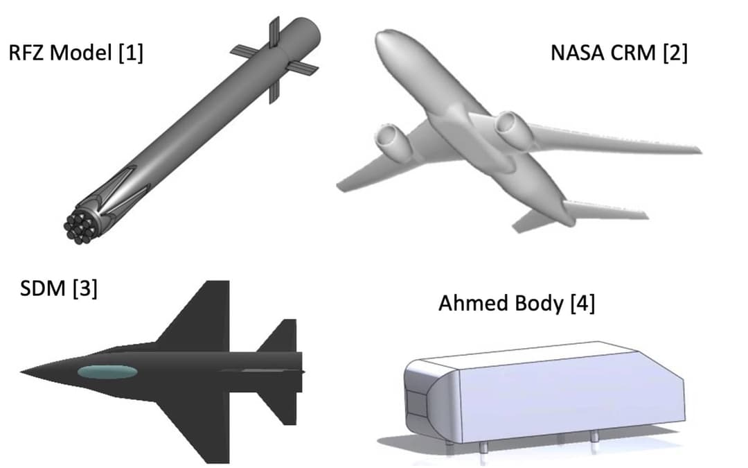
Aeronautical engineers have a long history of developing standardized models for wind tunnel calibrations and data comparisons between facilities. They are extremely useful in providing baseline datasets for correlation of results, data repeatability over time and verifying model installation or data acquisition systems. Reference models are also particularly relevant from the perspective of numerical analyses, where different codes can be directly compared with each other, or assumptions and solver settings can be experimented with to determine solution sensitivity to certain parameters. A standardized reference model typically fulfills two main criteria. Firstly, they are simplistic in shape with a precisely defined geometry, and secondly, they are representative of realistic configurations to ensure that the results are relevant. There are multiple examples of benchmark geometries which are available to aerodynamic engineers from various fields, including the Ahmed body for ground vehicles, the NASA CRM for commercial aircraft, the SDM for fourth generation fighters and the RFZ model, which is representative of modern launchers utilizing a re-usable first stage (similar to the Falcon 9).
Because the idea of having standardized models is longstanding, it is often the case that most of these models and the accompanying experimental data are spread over multiple reports, spanning decades, typically appearing in the form of scanned copies in old repositories. This leaves the modern engineer, who is used to having digital copies of all required data, with the task of digitizing plots and regenerating the model geometry based on drawings using a CAD package. Not only is this a significant time investment, but it also introduces potential sources of error into either the model or the experimental datasets being copied, due to the nature of digitizing poor-quality images. These facts have been the main motivating factor in the generation of an open source aerodynamic model, where at the click of a button, CAD geometries and experimental data can be downloaded from a file sharing platform, bringing the idea of standard aerodynamic models into the 21st century.
The SSAM-Gen5
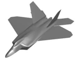
The SSAM-Gen5 is a new test case for a fifth-generation fighter aircraft. The CAD, CFD grids and experimental data can be downloaded from the Zenodo page found in ref [5]. This model is based on the F-22 Raptor and was chosen over the F-35 as the majority of in service fifth-generation vehicles have a twin-engine configuration. The geometry was generated from drawings and images of the aircraft that are openly available in the public domain. As such, the geometry is not intended to reproduce the aerodynamic characteristics of the F-22 Raptor, but rather, to reflect the salient aerodynamic features typical of contemporary aircraft. Geometric details such as the chordwise camber and spanwise twist were omitted to allow the vehicle geometry to remain as simple as possible while still representing the complex outer mold line of a fifth-generation platform. The wing profiles are four percent thick biconvex sections with sharp leading edges and no incidence angle. The sweep angle of the horizontal stabilizer and the main delta wing is approximately 42° with the twin vertical stabilizers swept back approximately 25° and canted outwards at an angle of 27.5°. The thrust nozzles are retained, while the intakes are simplified and sealed. The full-scale length of the vehicle is 19 m.
Work conducted to date
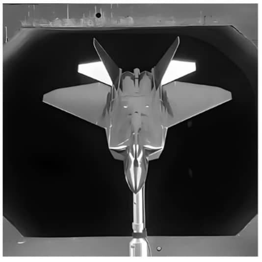
Subsonic wind tunnel tests were performed at the University of Sydney, with force and moment balance measurements used to develop a database of experimental validation data for the platform at a freestream velocity of 20 m/s. Numerical simulations using a variety of turbulence models on a grid converged mesh were completed using the commercial CFD solver ANSYS FLUENT. Investigations show strong correlations between aerodynamic coefficients from the wind tunnel and CFD up to an angle of attack (AoA) of 15 degrees, indicating that the basic experimental and computational approaches are valid. Past this point, the flow field is dominated by unsteady effects due to separated flow and the majority of steady-state RANS models appear to underpredict the loads measured in the wind tunnel [6].
Airshaper Comparisons
To gain some additional perspective on the vehicle aerodynamics from a second solver, a series of “regular” simulations using the Airshaper platform were completed. The results for lift, drag, pitching moment and aerodynamic efficiency had an extremely good correlation with wind tunnel data and the existing CFD database.
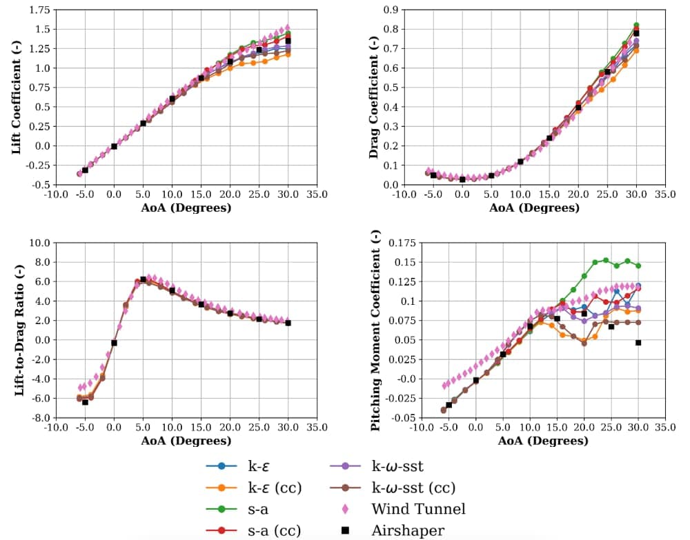
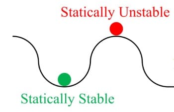
Analyzing the results, there are some clear aerodynamic characteristics which are typical of delta winged aircraft, such as the lack of stall behavior observed in the lift-coefficient plots. For aircraft with regular airfoils designed for subsonic flow (such as the NACA 4 or 5 series family), a lift coefficient peak is typically observed somewhere between 12 and 18 degrees AoA. As the AoA is increased past this point, severe flow separation occurs and causes the wing to stall. This manifests as a loss of lift and a negative lift curve slope. Contrary to this, the SSAM-Gen5 was tested up to 30 degrees AoA without showing any stalling behavior. This is due to the phenomenon of “vortex lift”, where the sharp, swept geometry of the leading edges promotes leading edge flow separation and vortex formation. Within the vortex cores, low pressure is observed and creates regions of suction along the wing. The reliance on vortices to generate lift, combined with the low aspect ratio wings results in a reduction in the lift-to-drag ratio, or aerodynamic efficiency, when compared with typical aircraft designed for subsonic operation. The final feature of note is the positive and non-linear gradient of the pitching moment coefficient, which indicates a statically unstable aircraft. An unstable aircraft tends to want to deviate from the trim point following a given control input, while a stable aircraft will want to return to the trim point. This fact can be easily explained using the ball analogy shown below, where any perturbation of the green ball will result in it resettling to its starting position, while the same action on the red ball will not.
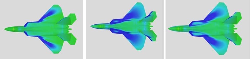
Commercial aircraft have strict design guidelines relating to static stability, however military aircraft often exploit unstable qualities to improve maneuverability. The positive pitching moment behavior suggests a nose up tendency of the vehicle and can be easily explained by looking at the surface pressure contours using the Airshaper online post-processing tool. The strength of the vortices increase with AoA, meaning that with every AoA increment, the centre of pressure (CoP) is shifting to a new location. For this vehicle, the regions of lowest pressure tend to appear towards the front of the vehicle (vortices formed at the leading-edge wing extensions/engine intakes), giving a CoP which is always located ahead of the center of gravity (CoG). The CoG has been estimated to be at about 35% of the mean aerodynamic chord.
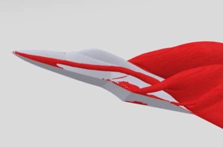
Between 15 and 20 AoA the formation of vortices along the nose are observed and can be seen in the image below for the 30 degree AoA case. Here it is clear that the systems of vortices result in an extremely complex flow field.
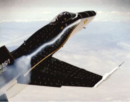
Until now, the influence of vortices has been discussed only within the context of global aerodynamic coefficients, however it is important to understand that loads induced on the airframe by these swirling flows can cause issues. A classic case of this was earlier variants of the F-18 which saw burst vortices interacting with the fins causing buffeting (see image below from ref [7]). Because the frequency of the burst coincided with the first bending mode of the fin, significant structural damage was seen and some fleets were grounded. This problem was fixed through the addition of a fence on the leading-edge extension, creating a secondary vortex to interact with the primary vortex, strengthening its core and preventing it from bursting. This highlights the importance of understanding vortex structures, their interactions with other flow features, as well as the ability to accurately predict their paths.
Moving back to the SSAM-Gen 5 results, there is a large spread in the CFD data when compared to the experimental data at high AoA. While the presented data has been corrected for blockage, there is some uncertainty about the accuracy of correction factors relating to non-traditional type aircraft, and this warrants further investigation. However, as strong agreement for lift and drag was observed across the AoA sweep, it is expected that the inherent sensitivity of pitching moment data, which relies heavily on both accurately predicting the total normal and axial forces as well as the locations where these forces are acting, plays a large role. It is well known that different RANS turbulence models are susceptible to large differences in modelling separated flows. Factors such as the size and shape of vortices as well as the prediction of vortex bursting is particularly critical. For the pitching moment coefficient, it was observed that there is a positively shifted curve in the experimental data at 0 degrees AoA. The gathered CFD results show unanimously that there is no pitching moment induced at this condition, meaning the drag of the fins above the CoG is offset by the drag of the sealed intakes below the CoG. It is suspected that there are some interference effects with the mounting strut in the wind tunnel that are causing this discrepency. Interestingly experiments for the SDM, a generic F-16 geometry, saw similar trends at the same condition where 0 degree AoA pitching moment predictions vary between -0.02 and 0.02 (see Figure 16 in ref [8]).
Future work
Due to the open source nature of this project, the opportunities for fellow researchers, students or hobbyists to complete their own aerodynamic investigations and contribute to the knowledge base surrounding fifth generation fighter aircraft is now easily achievable. Recommendations for further investigations stemming from this work include the evaluation of blockage effects at high AoA and interference from the model mounting system. Other areas of interest include the of the influence of Reynolds number variation on the aerodynamic coefficients, the investigation of unsteady computational methods, as well as the updating of the wind tunnel model to allow surface pressure tapping, facilitating direct comparisons on the vortex location with RANS data. General recommendations for further avenues of investigation include the generation of lateral-directional, control and dynamic derivatives. Experimental data for validation purposes outside of the subsonic incompressible flow regime and at Reynolds numbers more closely representative of full-scale in-flight conditions is highly desirable but relies on collaborations with other research institutions.
References
[1] The RFZ Model - A standard model for the investigation of aerodynamic and aerothermal loads on a re-usable launch vehicle, https://zenodo.org/communities/rfz-model/?page=1&size=20
[2] NASA CRM homepage https://commonresearchmodel.larc.nasa.gov/?doing_wp_cron=1694606395.0442950725555419921875
[3] Huang, X. Wing and Fin Buffet on the Standard Dynamics Model; Technical Report Defense Technical Information Center Compilation Part Notice ADPOI0722; Field Technology Inc.: Long Beach, CA, USA, 2000.
[4] Ahmed SR, Ramm G, Faltin G. Some salient features of the time-averaged ground vehicle wake. SAE Technical Papers ed. Warrendale: SAE International, 1984.
[5] SSAM-Gen5, https://zenodo.org/communities/ssam_gen5/?page=1&size=20
[6] Giannelis, N.F.; Bykerk, T.; Vio, G.A. A Generic Model for Benchmark Aerodynamic Analysis of Fifth-Generation High-Performance Aircraft. Aerospace 2023, 10, 746. https://doi.org/10.3390/aerospace10090746
[7] F-18 Leading Edge Extension Fences, https://aerospaceweb.org/question/planes/q0176.shtml
[8] Erm, L., An Experimental Investigation Into the Feasibility of Measuring Static and Dynamic Aerodynamic Derivatives in the DSTO Water Tunnel, Defence Science and Technology Organisation, 2013, https://apps.dtic.mil/sti/pdfs/ADA588964.pdf