
About the author
Tomáš Hájek holds a PhD in Aerospace, Aeronautical and Astronautical Engineering from the Brno University of Technology. He previously conducted wind tunnel tests, designed & tested ballistic recovery systems for aircraft, and is a fan of 3D printing and UAVs.
At Mejzlik Propellers, he heads the analysis and testing team, and that includes selecting & benchmarking new simulation & testing methods.
Wind tunnel test data
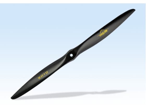
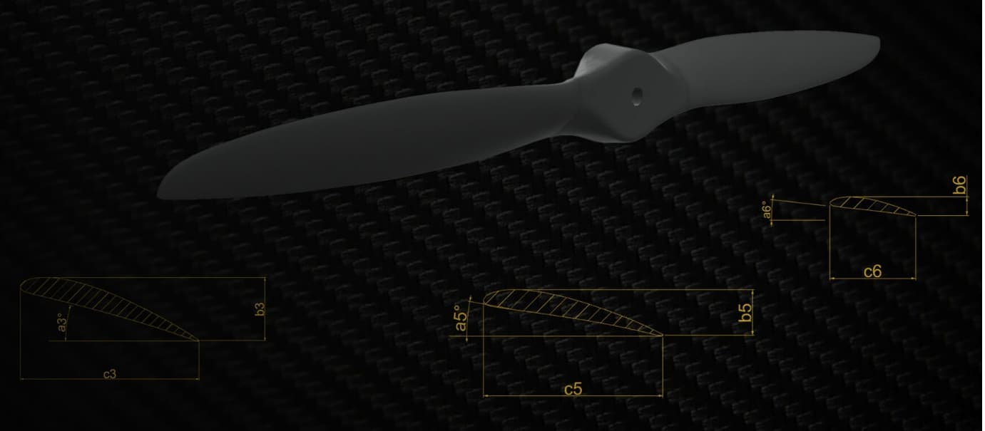
To validate AirShaper, we used wind tunnel test data for one of our existing propellers, the 21x13 CCW 2B E L. It has a diameter of 21” and a pitch of 13”, so it’s a fairly large propeller. Yet, it weighs under 40g.
The wind tunnel experiment was conducted in facilities at the University of Defence, Brno. The propeller was mounted onto a test stand in a puller configuration. A detailed description of the wind tunnel, test stand, and method is shown in an article of Rozehnal [1]. We then measured the power, torque & thrust while we increased the incoming wind speed from 0 to 35m/s (which translates into an advance ratio of up to 0.8). The propeller performed at a steady speed of 4900 RPM.
In-house simulation tools
Together with the Czech government & partners, we have developed our simulation tool to predict propeller performance. Our tool is based on methods that do not require heavy computing. It combines Lifting line theory, Blade Element Momentum (BEM) Theory, and Vortex theory. The tool is extremely fast. But comes with the general limitations of such methods, which struggle to accurately capture blade tip losses, cope with non-axial flows, etc.
But because we design all of our propellers in-house in 3D software, the step towards CFD simulations on AirShaper was an easy one for us.
AirShaper simulations
We used AirShaper to run the same sweep of CFD (computational fluid dynamics) simulations:
- Constant RPM of 4900
- Incoming wind speed varying between 0m/s and 60 m/s (advance ratio up to 1.38).
- 2 different accuracy levels: Basic (1 million cells) and Regular (10 million cells)
- Without prism layers and with prism layers
The entire sequence (domain sizing, automated & adaptive meshing, ...) is automated, so the procedure was identical for all simulations. That allowed for a perfect one-to-one comparison of the results.
Results
The most relevant data points have been summarized under the "Data" section at the end of this article. Below, the trends for the thrust & power coefficients as well as the efficiency are analyzed.
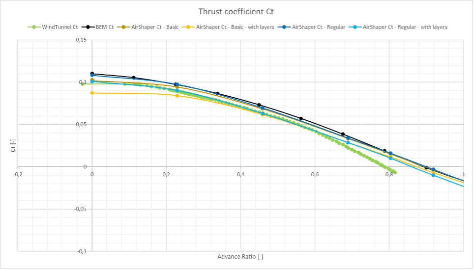
Thrust coefficient
All results are quite close to each other for the thrust coefficient. In this context, close means that for example, at an advance ratio of 0.4 all predicted values are within 12% of the measurement. The BEM method features the largest deviation. The Basic simulation with layers underpredicts the thrust at low advance ratios. Overall, the Regular simulation with layers features the best correlation with the wind tunnel data with a near-exact match up to an advance ratio of 0.6. All methods capture the correct trend.
The wind tunnel data indicates that the propeller starts windmilling (where the wind starts to drive the propeller instead of the other way around, generating a negative thrust) at an advance ratio J just below 0.8. The simulations predict this to happen at an advance ratio of around 0.9.
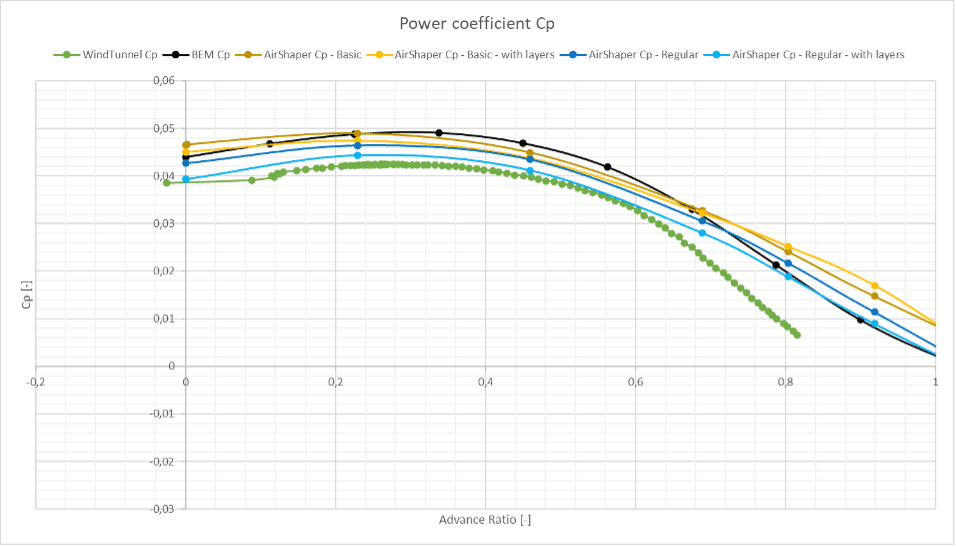
Power coefficient
All simulation methods predict a higher power coefficient than the measured wind tunnel values. In the context of the power coefficient, values are within 16% of the measurement. The BEM method (black curve) overpredicts the most, closely followed by the Basic simulation without layers (with layers, the Basic simulation gets a little closer). All methods capture the correct trend.
At higher accuracies (the Regular simulations) the results correspond best, especially when layers are applied to the simulation – this results in a near-exact match. Beyond an advance ratio of 0.6, the simulation results (both BEM and CFD) start to diverge from the wind tunnel data.
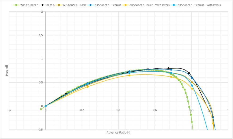
Efficiency
For advance ratios below 0.6, the BEM method corresponds well with the wind tunnel data. The Basic simulation with layers underpredicts the efficiency. The Regular simulation with layers shows a good correspondence up to an advance ratio of 0.7. All methods capture the correct trend.
Wind tunnel effects
For this test, the propeller was placed in an open test section, see the image below. This helps to reduce the blockage effect (see this video), as the pressures before and after the propeller disk can equalize with the atmosphere. According to Glauert [2], unless the propeller disk is bigger than 70% of the area of the cross-section, no correction is required.
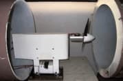
In the case of a propeller rotating at an RPM close to the “windmilling” point, however, it will start acting like a disc blocking the flow. In that case, the air needs to curve around the propeller and fit between the propeller and the opening of the wind tunnel. This leads to a pressure build-up ahead of the propeller, reducing the thrust it can generate.
The simulation data doesn’t suffer from this blockage effect, and thus at advance ratios close to the windmilling point, the results start to diverge. The solution to this could be to use a larger wind tunnel, place the propeller further downstream of the opening, etc.
Conclusion
We’ve seen that for advance ratios where the blockage factor doesn’t play a significant role (below the advance ratio of 0.6), all methods show a good overall correlation. As expected, the CFD methods outperformed the BEM method in accuracy, at the cost of a higher computational effort.
Within the CFD methods, the Regular simulations (10 million cells) with layers even provide a near-exact match between simulation and wind tunnel test data across the entire advance ratio range of 0.0-0.6. It is expected that in a properly sized wind tunnel, the correlation would further improve even for advanced ratios beyond 0.6.
The major benefit Mejzlik company sees in the CFD method is that it can be applied to full UAVs, including multiple propellers and their airframe. The interaction between propellers can be studied, the effect of prop wash onto the airframe, etc. This allows for designers to select the right propeller with the right wake structure for example, to improve the interaction with other propellers and the airframe. To us at Mejzlik, this allows us to advise our customers in much more detail on their overall design strategy, far beyond creating a better propeller. So we can provide a holistic aerodynamic design approach rather than simply providing them with propeller data.
Data
| Ct | ||||
|---|---|---|---|---|
| Advance ratio J [-] | 0.2 | 0.4 | 0.6 | 0.8 |
| Mejzlik | 0.0994 | 0.0799 | 0.0510 | 0.0163 |
| AirShaper - Basic - wo Layes | 0.0957 | 0.0762 | 0.0493 | 0.0186 |
| AirShaper - Basic - w Layers | 0.0842 | 0.0686 | 0.0452 | 0.0174 |
| AirShaper - Regular - wo Layers | 0.0989 | 0.0780 | 0.0501 | 0.0185 |
| AirShaper - Regular - w Layers | 0.0925 | 0.0714 | 0.0425 | 0.0099 |
| Wind Tunnel | 0.0918 | 0.0711 | 0.0411 | -0.0035 |
| Mejzlik | 108% | 112% | 124% | -459% |
| AirShaper - Basic - wo Layes | 104% | 107% | 120% | -523% |
| AirShaper - Basic - w Layers | 92% | 96% | 110% | -490% |
| AirShaper - Regular - wo Layers | 108% | 110% | 122% | -521% |
| AirShaper - Regular - w Layers | 101% | 100% | 103% | -280% |
| Wind Tunnel | 100% | 100% | 100% | 100% |
| Cp | ||||
|---|---|---|---|---|
| Advance ratio J [-] | 0.2 | 0.4 | 0.6 | 0.8 |
| Mejzlik | 0.0484 | 0.0485 | 0.0388 | 0.0204 |
| AirShaper - Basic - wo Layes | 0.0494 | 0.0465 | 0.0379 | 0.0247 |
| AirShaper - Basic - w Layers | 0.0467 | 0.0455 | 0.0384 | 0.0250 |
| AirShaper - Regular - wo Layers | 0.0467 | 0.0448 | 0.0363 | 0.0220 |
| AirShaper - Regular - w Layers | 0.0447 | 0.0425 | 0.0336 | 0.0196 |
| Wind Tunnel | 0.0417 | 0.0417 | 0.0321 | 0.0081 |
| Mejzlik | 116% | 116% | 121% | 250% |
| AirShaper - Basic - wo Layes | 119% | 112% | 118% | 303% |
| AirShaper - Basic - w Layers | 112% | 109% | 120% | 307% |
| AirShaper - Regular - wo Layers | 112% | 108% | 113% | 271% |
| AirShaper - Regular - w Layers | 107% | 102% | 105% | 240% |
| Wind Tunnel | 100% | 100% | 100% | 100% |
| Efficiency | ||||
|---|---|---|---|---|
| Advance ratio J [-] | 0.2 | 0.4 | 0.6 | 0.8 |
| Mejzlik | 0.4191 | 0.6637 | 0.7956 | 0.6777 |
| AirShaper - Basic - wo Layes | 0.3968 | 0.6520 | 0.7448 | 0.5545 |
| AirShaper - Basic - w Layers | 0.3643 | 0.6080 | 0.6627 | 0.5213 |
| AirShaper - Regular - wo Layers | 0.4375 | 0.6857 | 0.7981 | 0.6194 |
| AirShaper - Regular - w Layers | 0.4254 | 0.6574 | 0.7510 | 0.4967 |
| Wind Tunnel | 0.4452 | 0.6810 | 0.7745 | 0.2132 |
| Mejzlik | 94% | 97% | 103% | 318% |
| AirShaper - Basic - wo Layes | 89% | 96% | 96% | 260% |
| AirShaper - Basic - w Layers | 82% | 89% | 86% | 244% |
| AirShaper - Regular - wo Layers | 98% | 101% | 103% | 290% |
| AirShaper - Regular - w Layers | 96% | 97% | 97% | 233% |
| Wind Tunnel | 100% | 100% | 100% | 100% |
References
[1] ROZEHNAL, Dalibor, 2006. Experimental system for the small aircraft propeller testing. In: Engineering Mechanics 2006: Engineering Mechanics 2006. Book of extended abstacts. [online]. Svratka, Brno, Czech Republic: Institute of Theoretical and Applied Mechanics, Academy of Sciences of the Czech Republic [vid. 2024-05-20]. ISBN 80-86246-27-2. Dostupné z: https://www.engmech.cz/im/proceedings/show_p/2006/320
[2] GLAUERT, H., 1933. Wind Tunnel Interference on Wings, Bodies and Airscrews. In: [online]. [vid. 2023-03-15]. Dostupné z: https://www.semanticscholar.org/paper/Wind-Tunnel-Interference-on-Wings%2C-Bodies-and-Glauert/e1b4c6dc8ca7c627e7bae114821f45491fbb079c