A recent marketing campaign by the fluid pump manufacturer Grundfos [1] suggested that inefficient circulation pumps in homes are the third highest consumers of electricity, after freezers and tumble dryers. In their estimate, replacing 200 million old pumps around the world could save the equivalent of Portugal’s annual energy consumption of around 42000 GWh [2].
Outside the home, pumped fluid installations like this are widespread in industry and transportation across the world. Modern flow simulation software can now allow engineers to improve the internal flow characteristics of pumps and pipework that are key to achieving high system efficiency.
Why is understanding internal flow important?
Fluid flowing from one end of a pipe to the other end is the most understandable example of internal flow. The same physics applies to everything from a drinking straw to an oil drilling rig. More complicated systems such as air flow in the cylinder head of an engine, or coolant around a heat exchanger require more detailed analysis, but are affected by the same basic mechanisms.
Boundary layers
As a fluid is pumped around a system it is subject to the effects of the solid that is containing and directing it. This may be in the form of the walls of a pipe or the fins in a heat exchanger, either way, a boundary layer is generated.
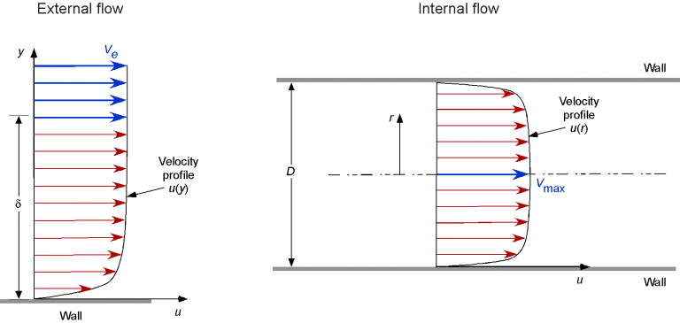
A boundary layer forms because the flow immediately next to the solid surface is effectively stationary and sticks to the wall. This creates a drag force on the fluid and consequently an increase in pressure drop from one end of the pipe to the other. This pressure drop represents an energy loss and therefore a reduction in efficiency.
For external flow, the fluid velocity increases to free stream velocity some distance away from the surface. Therefore, surface losses are generally less significant than form drag. Whereas for internal flows in narrow pipes, the whole flow is effectively within the boundary layer and so boundary layer losses are much more significant.
Effect of bends
A long straight pipe will generally contain laminar flow, where the fluid travels in the same direction. This is desirable from an efficiency point of view, but most systems require joints, bends and other discontinuities as part of their design.
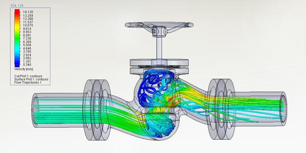
These features can lead to swirl, recirculation and flow separation that each contribute to a loss of energy in the flow and may lead to vibration and noise problems [3]. As flow moves around a bend, it applies a force to the surface of the pipe, effectively trying to straighten it, resulting in inefficiencies within the flow.
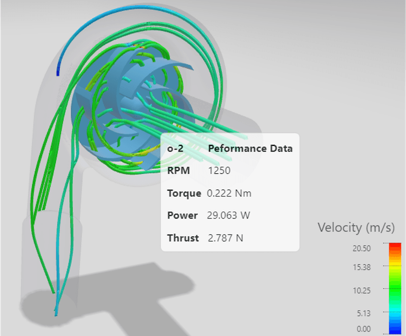
Driving the flow
Fluid circuits require a powered pump to create the pressure difference that drives the flow, in the same way that electrical circuits require a potential difference to generate a current flow. As fluid flows around the system, it experiences losses which remove energy from the flow, increasing the amount of energy the pump must supply. Optimising the behaviour of the internal flows within a system reduces this pumping requirement and therefore improves packaging, weight, energy consumption and cost.
How can CFD optimise internal flow?
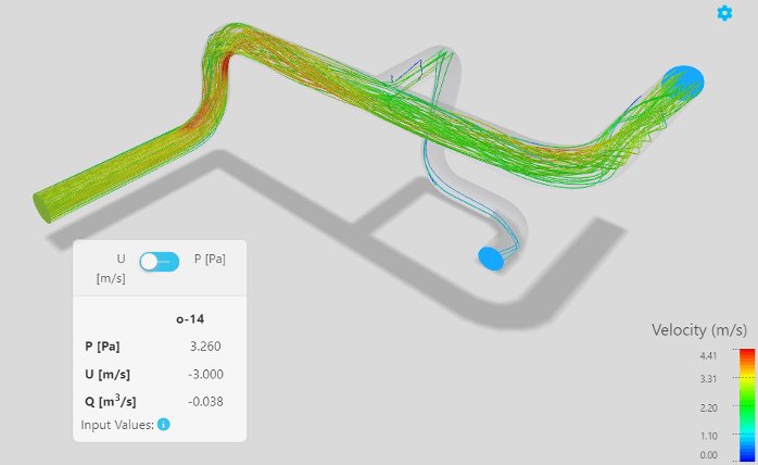
Computational Fluid Dynamics (CFD) simulation software uses numerical methods such as the Navier-Stokes flow equations to model and analyse fluid in and around bodies. Due to the complexity of the analysis, this is carried out using an iterative approach around a meshed (or discretised) 3D model.
As engineers continue to hunt for efficiency in pumps, engines and turbomachinery, accurately modelling internal flows has become a key focus over recent years. ‘This is why we have added the ability to analyse internal flows within AirShaper, because our customers see a growing need for it,’ highlights Wouter Remmerie, CEO at AirShaper.
‘Often, the external aerodynamics applications that customers use AirShaper to analyse end up involving internal fluid dynamics. In automotive for example, companies use CFD to simulate intake manifolds of engines or Heating Ventilation Air Conditioning [HVAC] systems as well as overall drag and downforce.’
The governing equations required to model internal and external flow are the same, the difference is in details such as boundary conditions, fluid properties and analysis outcomes. ‘For an external aerodynamics simulation, we normally look at the force on the object and iterate until it converges to something which is stable,’ says Remmerie.
‘We detect convergence automatically and then continue the simulation for an extra number of iterations to get a reliable averaged flow field. For internal flows, we just need to look at a different quantity. Instead of force, we look at the average flow speed through the system. The same mathematics detect convergence, but use a different metric.’
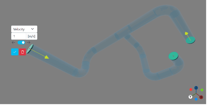
Airshaper’s user interface offers the same key benefits that make solving internal flow cases just as straightforward as external flow cases. ‘Many of the things that we developed for external aerodynamics, are applicable to internal flow,’ explains Remmerie.
‘Our adaptive meshing strategy for example, can be used to refine internal flow and find where the flow is more complex. Similarly, we can work directly with non-watertight 3D models using the techniques we developed for external flow. We want to provide the same functionality for internal flows, so users can quickly and easily upload a model, which may have some gaps, run an analysis and receive a detailed flow visualisation report.’
The advantages of fluid dynamics simulation software
The increasing availability of fluid simulation software and easy to use platforms such as AirShaper means that internal flow analysis is no longer limited to only high-end applications. New applications are being found all the time in almost every area. ‘CFD should not be a niche tool, available only to a few,’ concludes Remmerie.
‘Our goal at Airshaper is to make CFD available to as many people as possible, without requiring in-depth knowledge of the complicated physics and mathematics that underly it. In this way, we can help engineers, designers and aerodynamicists work on new and emerging applications and technologies across a variety of different industries.’
Interesting links:
- CFD Analysis of an Electric Motor's Cooling System
- CFD Port Flow Simulation of Air Flow Rate in Spark Ignition
References
[1] 2023. 200 Million Possibilities Campaign Press Release [Online]. Grundfos
[2] 2023. Monthly Balance [Online]. Redes Energéticas Nacionais
[3] A,A., 2020. Flow-induced vibration in piping systems [Online]. Process Instrumentation