Wind tunnels are one of the most important tools in an aerodynamicist’s armoury. They bridge the gap between real world aerodynamic testing and CFD simulation, allowing aerodynamicists to test physical parts in a more controlled environment. But how do wind tunnels work and what techniques should you use to achieve reliable and accurate results?
A brief history
During the 19th century, research into aerodynamics was largely aimed at manned flight. The physical testing at this time involved a whirling arm, often gravity powered, which rotated a test object through the air. It was eventually realised that this rotation generated a circular wake that affected the accuracy of the results, so a new testing approach was required.
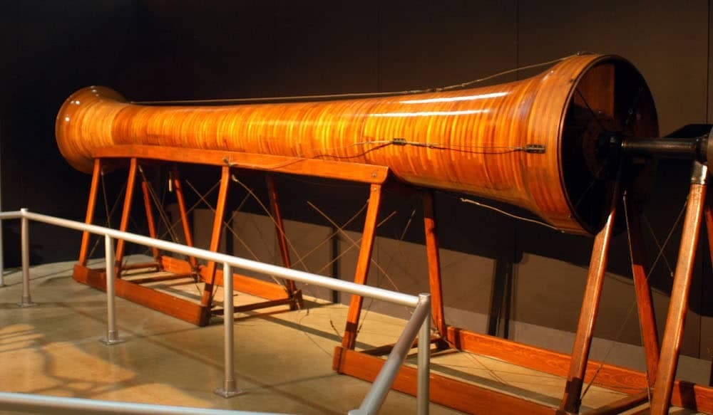
In response, Frank Wenham built the world’s first wind tunnel in 1871 [1] which was a 12ft (3.7m) long tube with a fan blowing air along its length. As aircraft and ground vehicles continued to develop, so did the capabilities of wind tunnel testing and by 1916, the Wright Brothers were utilising a larger tunnel with improved flow velocity and quality.
Aeronautical engineering continued to progress quickly and by 1920, NACA were building a 5ft (1.5m) wind tunnel based on a British Royal Aircraft Establishment (RAE) tunnel [2]. However, the need for better measurement techniques to match scientific understanding meant these tunnels quickly became obsolete.
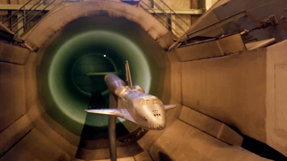
Over the last 100 years, aircraft have developed into faster and larger vehicles, so to conduct accurate testing, wind tunnels have had to evolve too. The largest wind tunnel in the world is currently NASA’s Ames Research Center which can test aeroplanes with wing spans of up to 100ft (30.5m) [3]. While the accuracy of results now means that wind tunnels can be used to test anything from space shuttles to athletes.
How does a wind tunnel work?
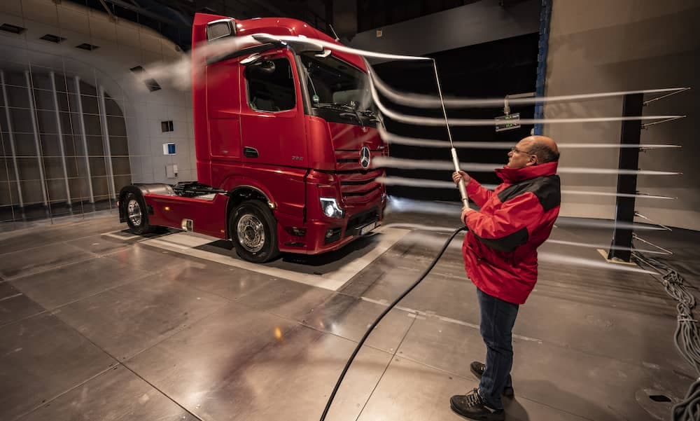
Whether it is a plane or a racecar, fundamentally it is an object moving through air. However, to replicate the behaviour of the airflow around an object, wind tunnels flip this around and move air over a fixed object.
Wind tunnels come in a range of layouts, sizes and speeds to cater for the many different applications of wind tunnel testing. The most common is the closed loop wind tunnel, variations of which form the basis of most aeronautical and automotive facilities. To understand the basics of wind tunnels, let's consider a subsonic, pressurised wind tunnel such as the ONERA wind tunnel in France.
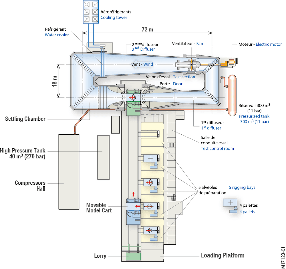
This type of tunnel circulates a mass of air around a closed-loop circuit and flows high speed air over the object in the test section. This object could either be a scale model or full-size vehicle. This wind tunnel loop can be broken down into four main areas:
- Fan
- Cooling
- Flow conditioning
- Test section
Moving the air
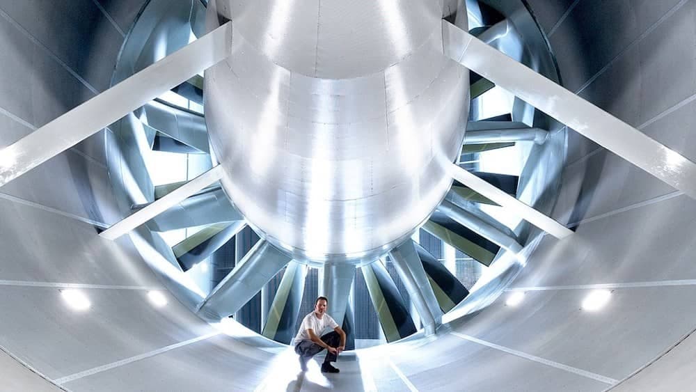
At the heart of the wind tunnel is the fan, which needs to be extremely powerful to achieve the flow velocity required at the test section. This results in large, multi-bladed fans with variable speed and sometimes variable pitch propellors. They can be over 15m (49ft) in diameter and are driven by electric motors rated up to 10MW. The larger the fan, the higher its efficiency but the more difficult it is to build and house.
Cooling the air
As the air moves around the wind tunnel, it generates friction with the walls. This, together with the pressurised nature of the majority of wind tunnels causes the air to increase in temperature. To make sensitive measurements, temperature control is very important for both the air flow and the instrumentation. This is why tunnels of this nature have very powerful cooling systems, usually liquid based, and a radiator matrix through which the air flows.
Conditioning the flow
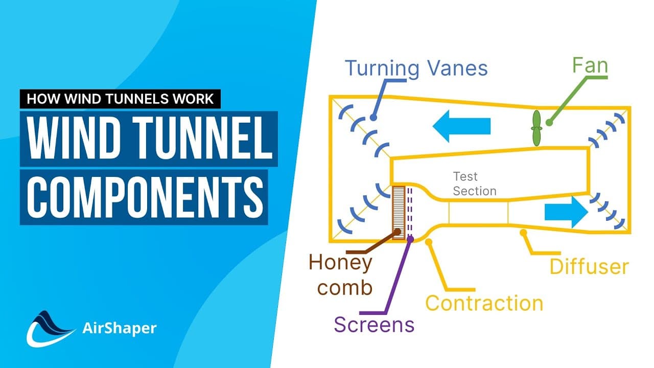
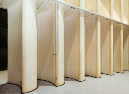
To maximise the flow at the test section, the air needs to travel around the circuit as efficiently as possible and minimise any losses. To help the air turn round corners efficiently, a series of aerofoil-section vanes are fitted to each corner to help bend the flow through 90 degrees with minimal loss in velocity.
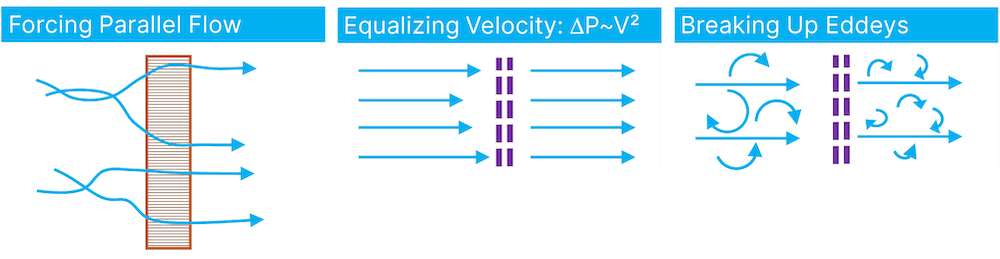
After the air has turned the final corner, it enters the settling chamber where the flow is conditioned to be as straight and turbulent free as possible. This is achieved using a honeycomb structure where tubes force the flow to be parallel and minimise swirl. The air then passes through a series of mesh screens which help to reduce variations in longitudinal flow velocity and break up an eddy currents.
Accelerating the flow
The last stage the air has to go through before entering the test section is a Venturi. Shrinking the diameter of the wind tunnel down to the cross sectional area of the test section, accelerates the flow to the required test speed. Downstream of the test section, the cross section is progressively increased through a diffuser expanding the flow and slowing it down again.
The test section
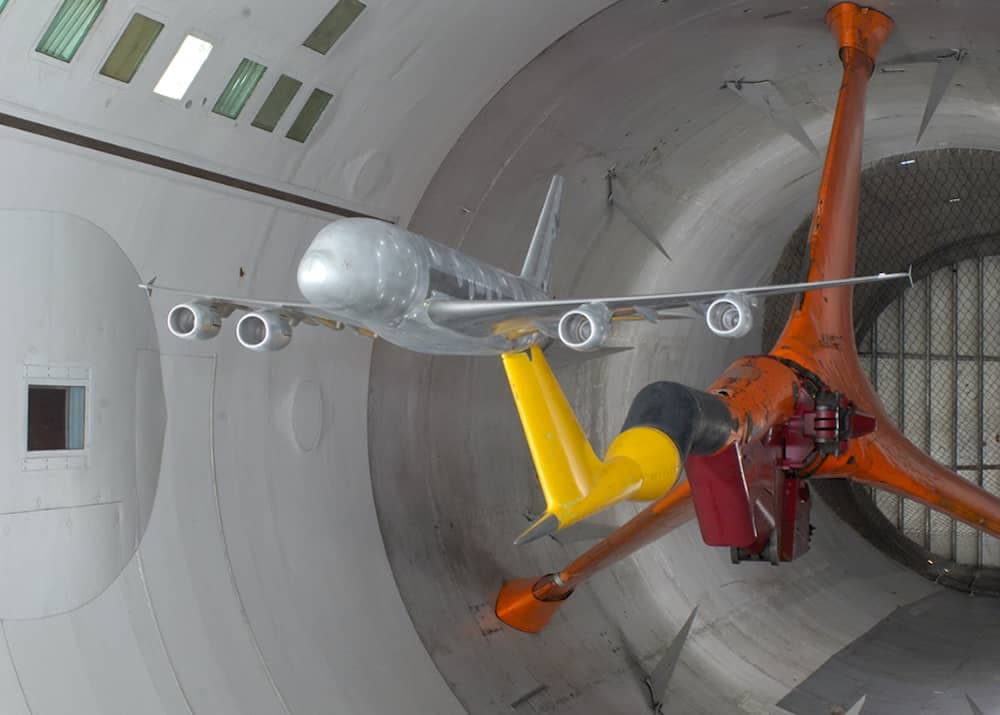
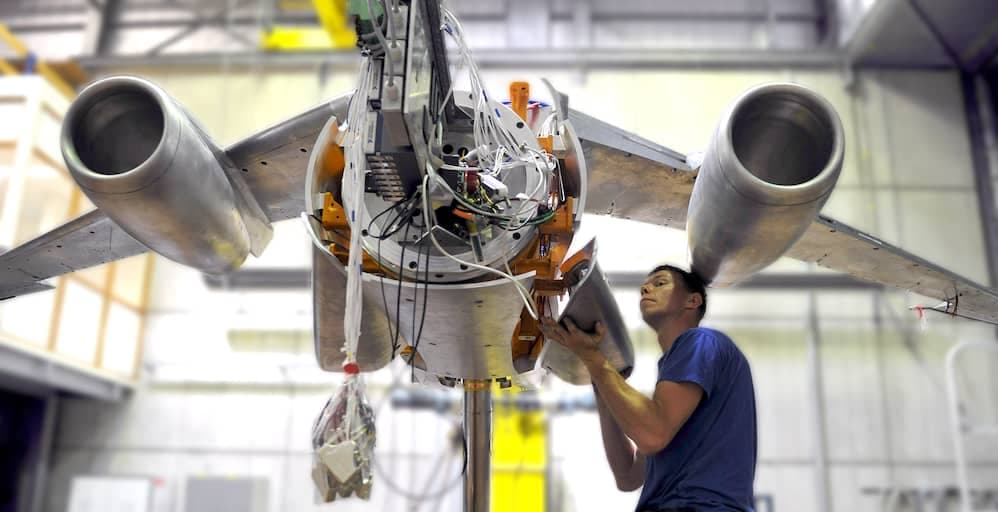
The test object is mounted in the wind tunnel test section. If the object is an aircraft, it will be mounted via a sting in some manner, typically from the rear. The sting is used to run instrumentation connections to and from the model and to move it through different test attitudes whilst measuring loads.
If the object is a full scale ground vehicle, it will usually sit on load measuring pads or a rolling road. The latter is more accurate as it allows the wheels to rotate at speeds that match the tunnel speed. Whereas, scale model road vehicles are often suspended just above the ground. In either case, the interaction with the ground plane is essential to model as the vehicle operates in a boundary layer in the real world that must be replicated in the wind tunnel.
Scale models
It is relatively unusual to test at full scale as the costs associated with a large enough facility are prohibitive. Therefore, companies often opt for scale model wind tunnel testing. This allows aerodynamicists to make quick iterations during test programmes, the parts are faster and cheaper to manufacture and scale models are overall easier to work on.
Scale models are typically 10-50% of full size, depending on the application. Large aircraft models are at around 10%, while road cars are often at 50% scale. But regardless of the scale, wind tunnel models are highly accurate with refined external geometries and a high standard of build quality to minimise the effect of any discontinuities on the results.
Internally, the models are full of instrumentation. This could include the load balance, which is responsible for measuring the lift and drag forces as well as the yaw, pitch and roll moments. Pressure tappings will be implemented on the surface of the model to measure static pressure, all of which have to be connected via rubber tubing to a pressure scanner.
The wind tunnel itself will also have a range of measurement techniques available. The forces on the model may be measured through the floor or the sting, rather than inside the model. While there are a a number of flow visualisation techniques such as Particle Image Velocimetry (PIV), smoke jets and flow visualisation paint. These help aerodynamicists visualise the behaviour of the flow to further their understanding.
Interesting links:
References
[1] Wind Tunnels of NASA. Chapter 1 - Whirling Arms and the First Wind Tunnels [Online]. NASA.
[2] Smith, Y. 2015. The NACA's First Wind Tunnel [Online]. NASA.
[3] 1992. NASA's Wind Tunnels - IS-1992-05-002-LaRC [Online]. NASA.