Over the years, engineers have been pushing the boundaries of wind tunnel technology to achieve accurate, reliable and repeatable testing. This has resulted in the development of a variety of different types of wind tunnel, each with their own advantages and disadvantages.
However, whatever the wind tunnel type, the most important area is the test section. This is where the item being tested is positioned and measured. Consequently, it's vital to achieve good flow characteristics in this area including low turbulence intensity, uniform flow velocity and a thin boundary layer.
Open circuit tunnels
Early wind tunnels were what are now referred to as open circuit tunnels. These variants essentially pull air in at one end of a building and exhaust it from the other. This makes them relatively cheap and simple to build, but are generally not used for very high accuracy applications. They are expensive to run and also don’t produce the best flow quality because they are always processing fresh intake air.
Closed circuit tunnels
Closed circuit tunnels, on the other hand, recirculate the same air mass around a closed loop, saving energy. In doing so, once initially up to speed, the fan is only needed to make up for losses as the air travels round the loop. However, one of the disadvantages of this type of tunnel is that the air is heated as it circulates, and so requires cooling.
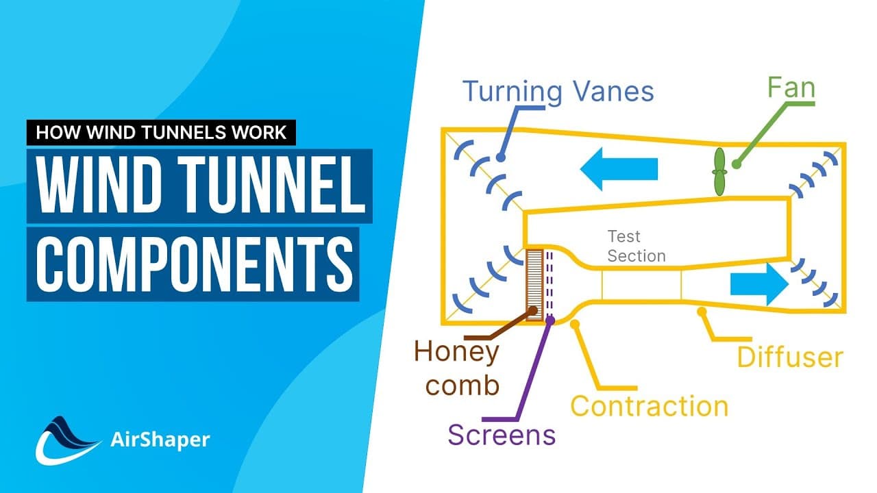
This type of tunnel is generally designed to generate much higher quality flow and so are more complicated and expensive to install. A typical layout consists of a fan, turning vanes, a cooler, a settling chamber and a series of grids and meshes.
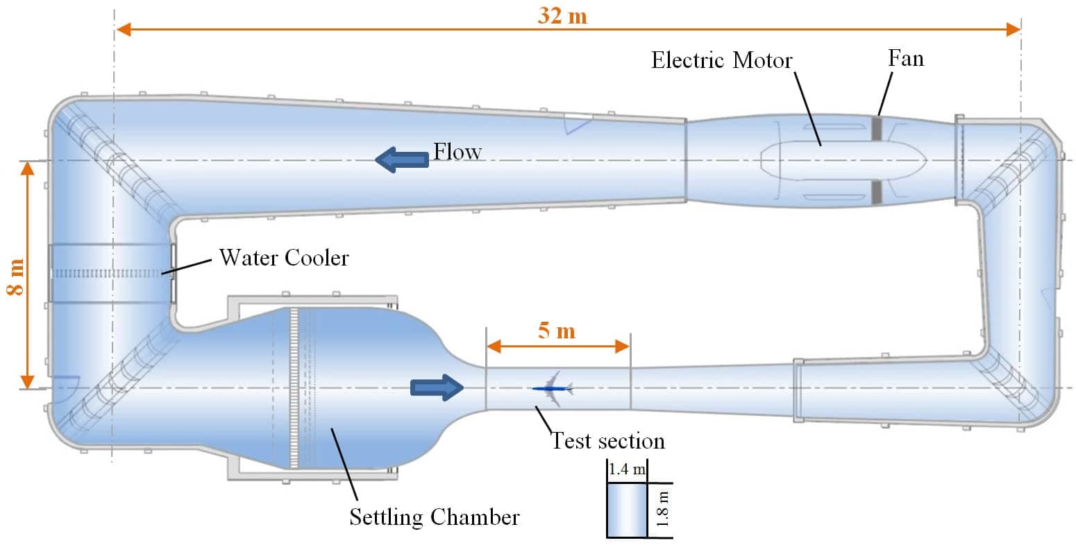
The fan is driven by an electric motor, which for larger applications can have a power of up to 1MW. The turning vanes are located at each corner of the loop and help turn the flow cleanly with as little loss as possible. While a series of grids and meshes straighten the flow and reduce turbulence in the settling chamber.
Pressurised / Variable density
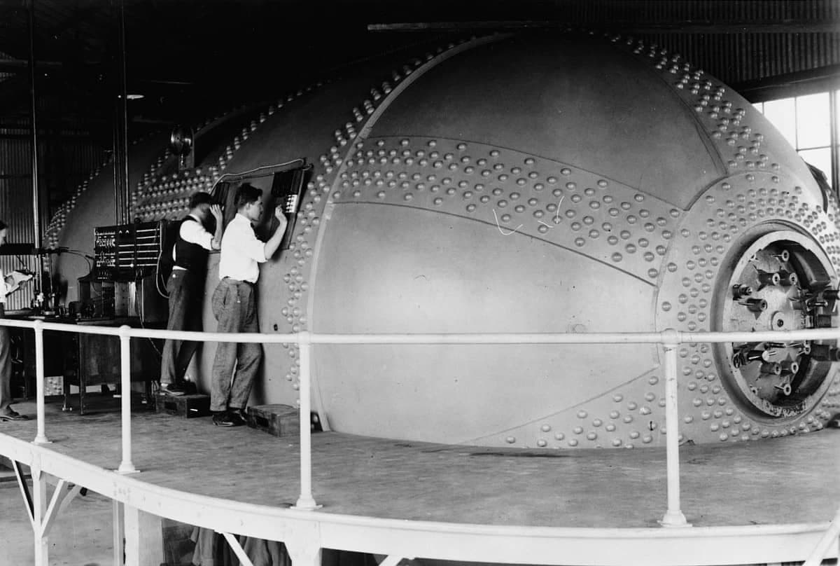
Another type of tunnel is the pressurised, or variable density tunnel. This is designed to make use of the density term of the Reynolds number calculation. By pressurising the air in the tunnel its density increases which allows high speed-equivalent testing in a tunnel with a lower air speed capability.
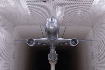
These tunnels are often used for high-speed aircraft testing where matching Mach number and Reynolds number together can be very important. Other tunnels use gases like super-cooled nitrogen to achieve the same effect. It is often surprising how long these technologies have been around, as the NACA variable density tunnel from the 1920s below highlights.
Closed circuit, open section
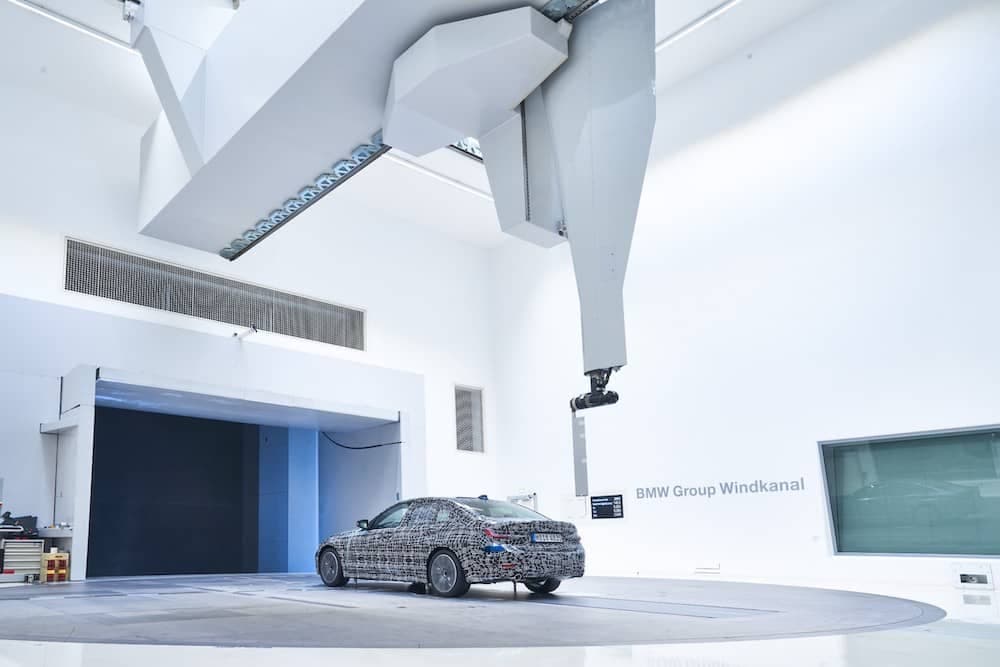
Many tunnels have an open test section, particularly when they are used for full size applications like road cars. They tend to have very large test sections with no walls close to the test item. This makes them very flexible, at the sacrifice of some accuracy.
The nature of this type of tunnel lends itself to climatic and aero-acoustic tunnels. Climatic tunnels can vary the humidity as well as run at temperatures between -35degC to +50degC. Although, these tunnels are usually used for durability testing rather than ultimate aerodynamic performance.
Aero-acoustic tunnels have anechoic working sections and are used to identify sources of audible noise. This helps road car manufacturers tune the interior and exterior design of vehicles to improve the cabin environment for passengers.
Closed circuit, closed section
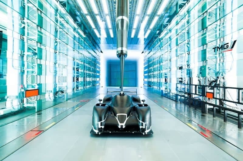
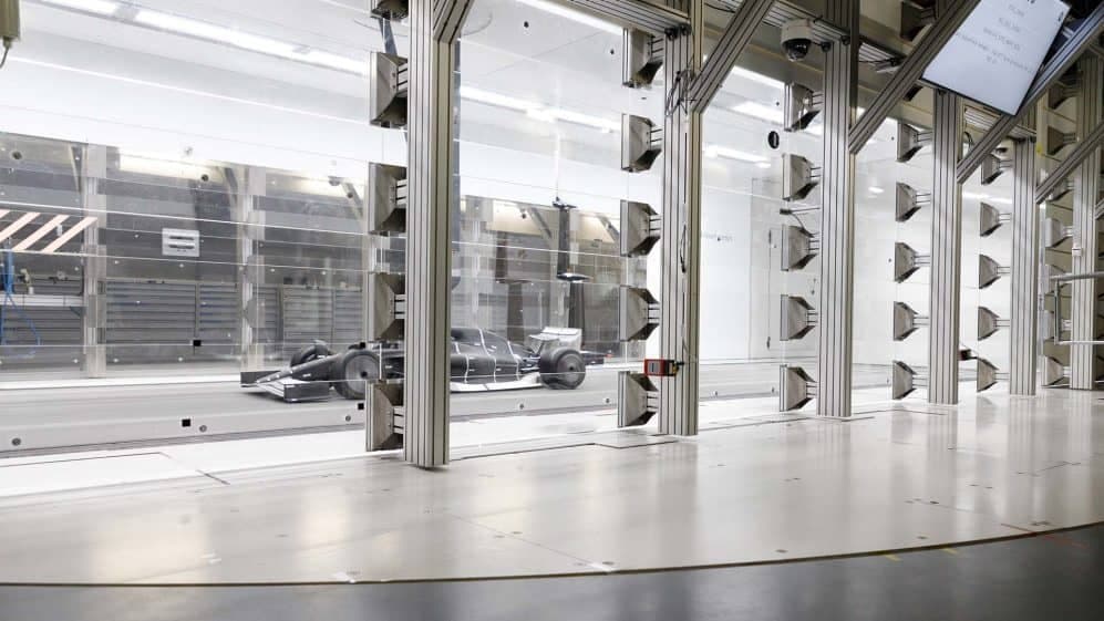
High end wind tunnel testing for aircraft and Formula One cars tends to be carried out using a closed-circuit, closed section tunnel. These are very expensive to build but produce a controlled testing environment which gives good accuracy and repeatability. They have a narrow range of acceptable temperature, average flow speed and flow straightness. These metrics are carefully monitored and tracked to ensure repeatable testing.
Closed circuit test section tricks
There are two main issues that affect the test section, these are the blockage ratio and the boundary layer. If either of these are not controlled correctly, they can lead to unrepresentative test results. The same applies to the control of shock waves in transonic wind tunnels which are designed to test the aerodynamics of vehicles that operate near the speed of sound.
Careful design along with new technologies can help solve these problems. For example, wind tunnels used for Formula One testing have adaptive walls, which are made up of different sections. Each section features pressure tappings and can also be moved to create a curved wall which better accommodates the flow. This allows for a larger test model to be installed than would otherwise be impossible.
Porous walls
A common problem when testing aircraft in wind tunnels is the transonic region. This is where the aircraft, or flow over part of the aircraft, is operating near the speed of sound. The shock wave - the sonic boom associated with supersonic aircraft - reflects off of the tunnel walls. This interacts with the normal tunnel flow and can cause correlation issues.
One solution is to use have variable porosity walls which are tuned to suit the application. The porosity allows the overpressure from the shock wave to exit the flow path rather than to reflect back.
Boundary layer control
There are a variety of tactics to control the boundary layer, but there are two common approaches. The first is to use a moving ground plane, usually a steel belt. This usually moves at the same speed as the free stream air, but can also be varied to mimic head or tail winds. The belt may also be textured to generate a more accurate turbulence level.
These belt assemblies are impressive pieces of engineering and are often able to rotate relative to the oncoming air stream. This allows for the model to be tested in yaw.
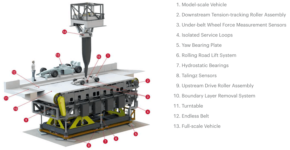
The second method of controlling the boundary layer is to use a vacuum system just before the working section. This removes air from the boundary layer and vents it downstream. The system will be tuned to generate a desired boundary layer depth at the model. This can be applied to the floor, walls and ceiling of a tunnel, depending on the application.