What are vortex generators and how can they be used to avoid flow separation?
We'll explore how vortex generators work and also demonstrate how you can use them to improve aerodynamic performance.
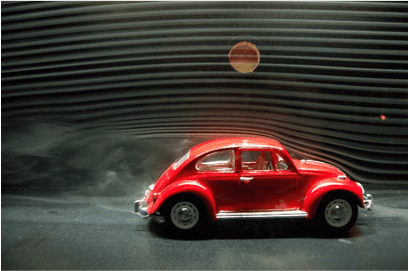
In our previous article on flow visualization techniques, we used wool tufts on a VW Beetle and discovered that flow separation was occurring over the rear window. This was the result of an adverse pressure gradient on the roofline boundary layer.
Boundary layer
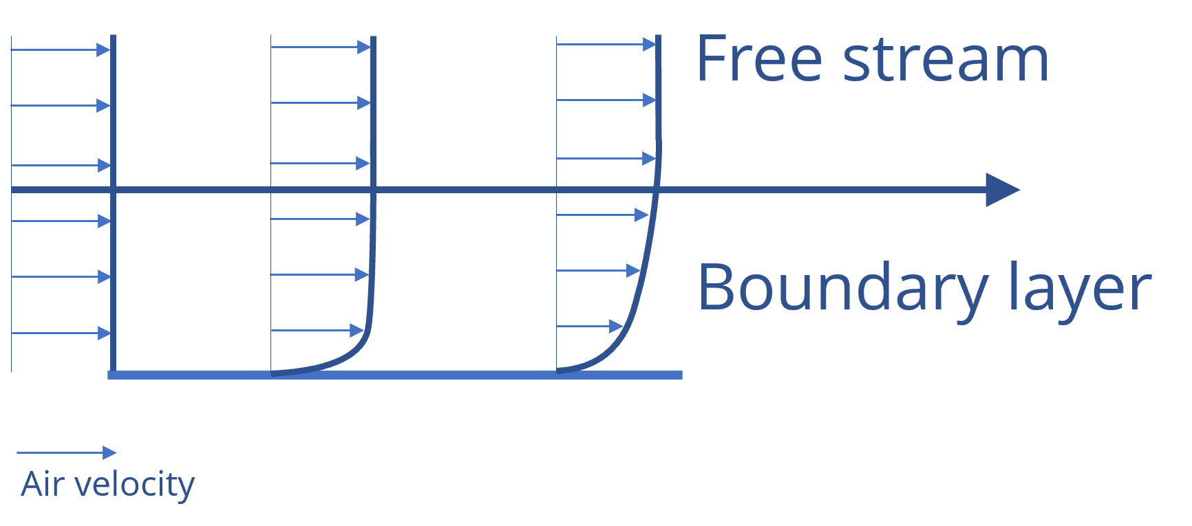
Every fluid has viscosity, or the tendency to resist flow. This results in the generation of friction forces that slow down air when it flows past an object. At the surface, this velocity is zero, which is referred to as a “no slip condition”.
The transition zone between the stagnant air at the surface and the unobstructed free stream air is known as the boundary layer. Air in this region is slow moving and contains less energy and momentum than the free stream above.
Flow separation
Flow separation is caused by an adverse pressure gradient. When air in the boundary layer moves towards an area of higher pressure, it loses velocity and energy. After a certain point, it is no longer able to follow an object's upper surface. We observed this in our Beetle flow visualization test where the tufts on the rear window moved erratically and unpredictably.
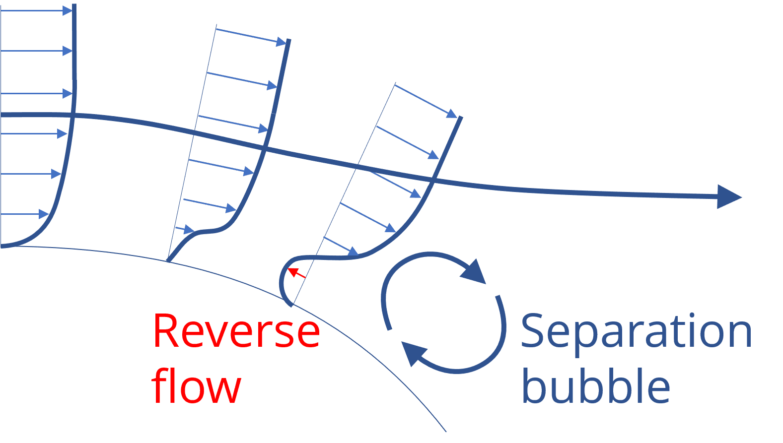
This detachment of flow creates a large turbulent wake directly behind the roofline. The volume of air being dragged along in the wake leads to a low-pressure pocket that pulls back on the vehicle and creates significant drag. High drag vehicles are slower and require more fuel consumption which is why preventing flow separation has become a major priority for manufacturers. One innovative method aerodynamicists use to achieve this is to install vortex generators.
Vortex generators
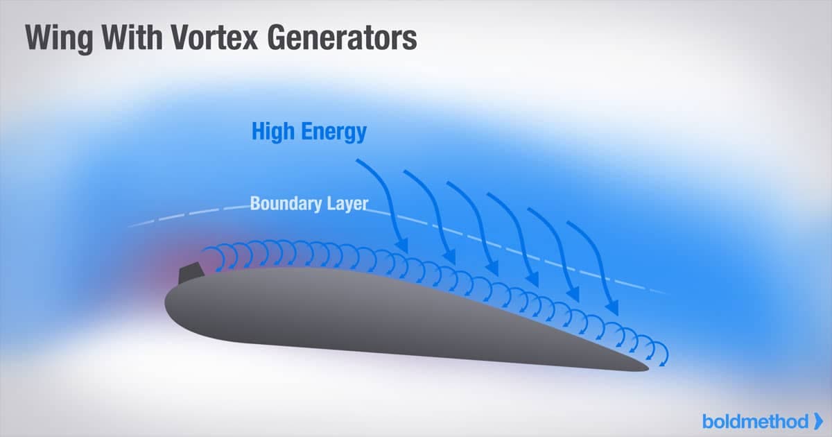
The purpose of a vortex generator is to re-energize airflow in the boundary layer to delay separation. This is achieved when a vortex moves across the boundary layer, mixing it with the high-speed freestream air above. Injecting this high energy flow of the boundary layer gives it more momentum to follow the curvature of an object.
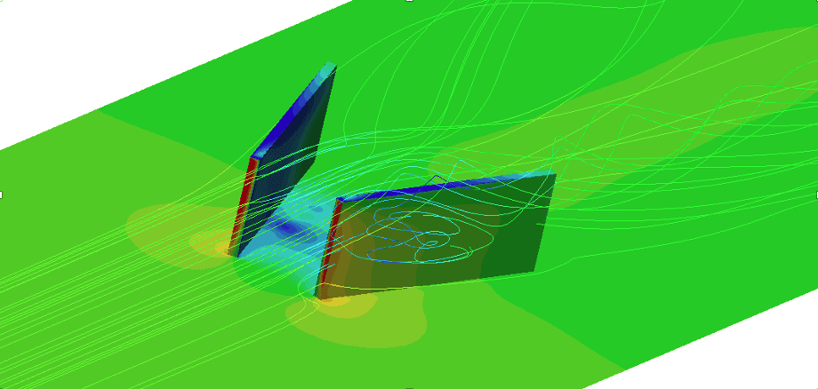
There are many ways to achieve this vortex. A simple example is a series of small vertical plates, placed at a slight angle of attack to the airflow. This angle increases the pressure at the leading edge of the plate and decreases the pressure at the trailing edge; creating a net pressure gradient.
Air prefers to move towards a favourable pressure gradient, or from areas of high pressure to low pressure. This causes it to spill over the sides of the plate to the low-pressure area behind, creating vortices in the process. This is the same phenomenon that drives wing-tip vortices, which you can read about in our winglets article.
In that case, the goal was to eliminate the creation of vortices as they reduced the effectiveness of the wing and induced drag. The vortices created by vortex generators are no different, and they too create their own drag. However, this penalty is overcome by the drag reduction effect from reducing flow separation and wake size, resulting in a net performance gain.
The key takeaway is that vortex generators should only be added when necessary, such as when flow separation is present. Adding them for the sake of it will only hurt aerodynamic performance. For this reason, it is also important that the vortex generators are the minimum size required. Any larger creates unnecessary drag.
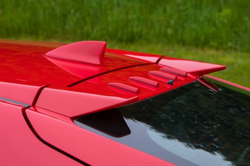
A good rule of thumb is that a vortex generator should be the same height as the boundary layer. This allows it to sufficiently draw from the freestream air above. As a reference, most vortex generators on production vehicles range from 20-30mm in height. As always, some experimentation may be necessary to find the optimal solution.
Demonstration
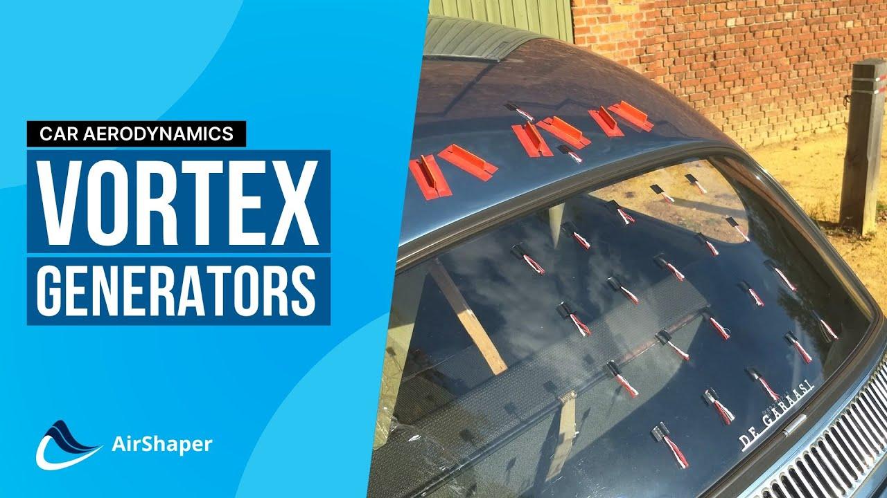
In the flow visualization techniques video, we saw evidence of flow separation on the rear window of the VW Beetle. In this video, we installed some homemade paper vortex generators to energize the boundary layer across the roof and delay separation. After some experimentation with position and distance, we found a configuration that worked well.
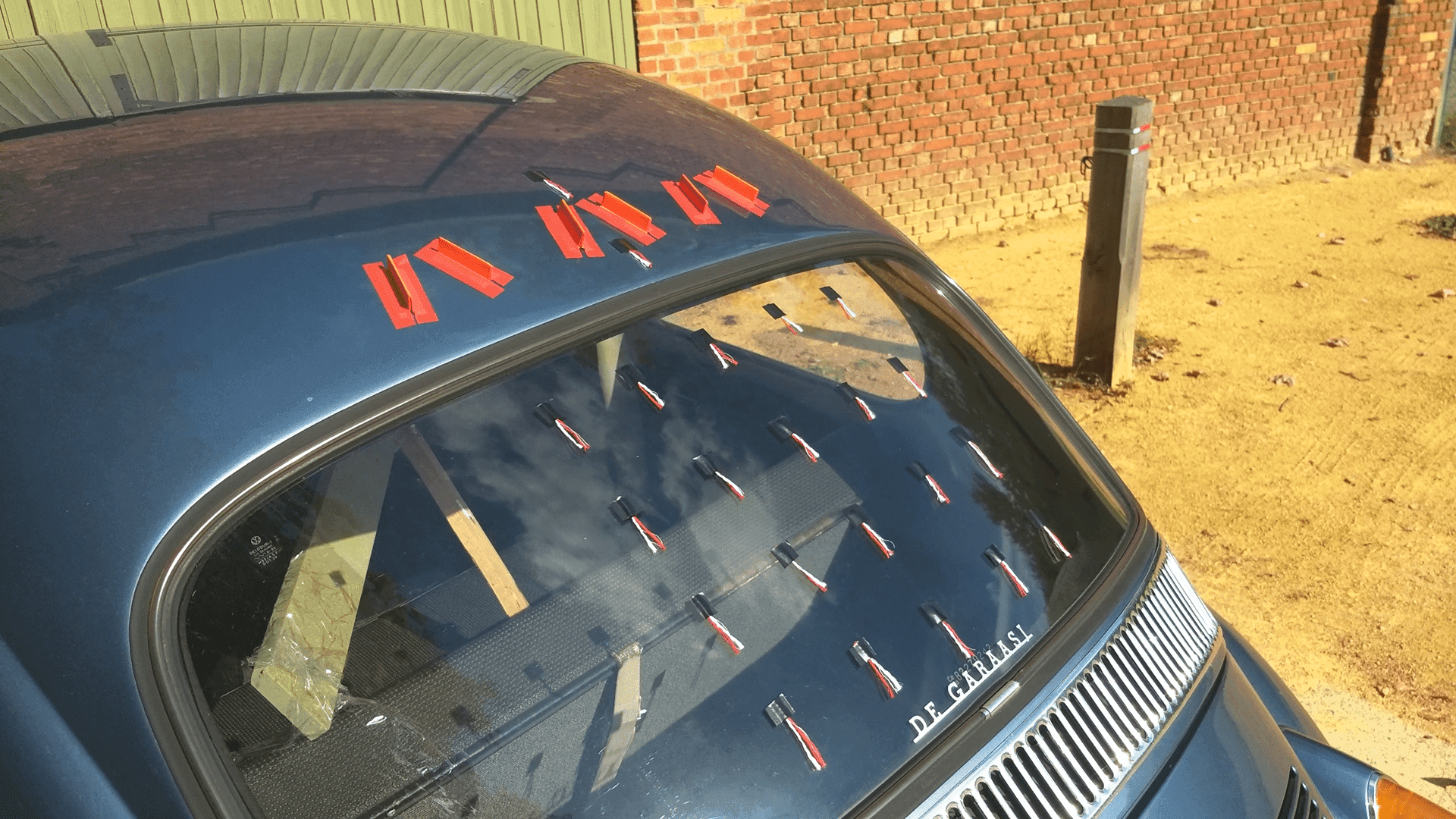
The results of the test can be seen below. The red and green zones represent the range of motion exhibited by the tufts without (red) and with (green) the vortex generators. As you can see, the motion of the tufts was significantly more controlled and orderly with the addition of the vortex generators. This indicates reduced flow reversal, resulting in reduced flow separation and likely lower drag!

Summary
In our previous piece, we demonstrated how easy visualization techniques can be used to understand the aerodynamics of a vehicle. Now, we have explored ways to improve performance using simple vortex generators. With this information, you can now perform aerodynamic tests on your own vehicle and improve performance using nothing but household items!
